Lead acid Battery

The 6-EVF-135 12V135Ah is a sealed 12 V AGM valve-regulated lead-acid block rated at 135 Ah on the three-hour rate — 45 A for three hours down to 1.75 V per cell — with a published weight of 45 ± 0.2 kg, published dimensions of 338 × 172 × 280 mm, a maximum charging current of 27.0 A, float setting 13.5 V and equalising setting 14.1 V, and a stated cycle life of 350–600 cycles at 50–80 % depth of discharge.

It is built for electric sightseeing vehicles, low-speed shuttle carts, hotel and resort runabouts and airport apron buggies: vehicles that work long days in heat, stop and start constantly, sit idle at full charge overnight, and then need to be back on the road at dawn.

Two numbers decide whether the 6-EVF-135 is right for your fleet. The first is the capacity rate: 135 Ah is a three-hour figure, so a bank sized on the ten-hour rate of this block will feel roughly a third smaller in the hills than the label suggests. The second is the 27.0 A charging ceiling, because a charger chosen from a generic “C10 charging” rule of thumb will over-charge this block every single night.

The complete published data set for the 6-EVF-135 12V135Ah sits on the 6-EVF-135 12V135Ah model page, and the rest of the sealed mobility range is listed under EVF sealed lead-acid batteries.

Key Takeaways

  • 135 Ah is a three-hour rating, not a ten-hour rating. The 6-EVF-135 delivers 135 Ah at C3, which means 45 A for three hours to a 1.75 V per cell cutoff (Model page). Sizing a pack on C10 will understate the real available energy in a hill climb.
  • The charging envelope is fixed and it is not generous. Maximum charging current is 27.0 A, roughly 0.20 × C10 on a 135 Ah block (Model page). A 30 A charger matches the datasheet; a 45–50 A charger does not.
  • Float and equalising are set for the 12 V block, not the cell. Float 13.5 V, equalising 14.1 V — that is 2.25 V and 2.35 V per cell across six cells (Model page).
  • Weight and footprint are what the vehicle designer needs. 45 ± 0.2 kg, 338 × 172 × 280 mm, φ20-M8 terminals (Model page). A 48 V pack of four sits on the floor at 180.0 kg (4 × 45 kg, Arithmetic).
  • Cycle life is a band, not a number. 350–600 cycles at 50–80 % depth of discharge (Model page). A fleet that keeps the pack between 50 % and 80 % full lives at the top of that band; a fleet that runs to near-empty every cycle lives at the bottom.

§1 — 6-EVF-135 12V135Ah Published Specifications

Parameter6-EVF-135 published valueSource
Product typeValve-regulated lead-acid, AGM technologyModel page
Nominal voltage12 V (six cells in one block)Model page
Rated capacity135 Ah at the 3-hour rate (C3), end voltage 1.75 V/cellModel page
Energy at nominal1,620 Wh (12 V × 135 Ah)Arithmetic
Weight45 ± 0.2 kgModel page
Dimensions (L × W × H)338 × 172 × 280 mmModel page
Terminalφ20-M8Model page
Maximum charging current27.0 AModel page
Float charge voltage13.5 V (2.25 V/cell)Model page
Equalising charge voltage14.1 V (2.35 V/cell)Model page
Designed cycle life350–600 cycles at 50–80 % DoDModel page
Specific energy36.0 Wh/kg (1,620 Wh ÷ 45 kg)Arithmetic
StandardsGB/T 32620.1-2016, GB/T 32620.2-2016, JB/T 2599Model page
CertificationsCE, RoHS, REACH, MSDS, IMDG sea-freight certificationModel page
48 V pack (4 × 6-EVF-135)180.0 kg (4 × 45 kg), 540 Ah, 6,480 Wh, 108 A charge limitArithmetic
72 V pack (6 × 6-EVF-135)270.0 kg (6 × 45 kg), 810 Ah, 9,720 Wh, 162 A charge limitArithmetic

Every row above carries the source it came from. The values marked Model page are taken from the published 6-EVF-135 product page; the rows marked Arithmetic are simple multiplications of those published values and nothing else — no value in this table has been estimated, rounded up for marketing, or carried over from a neighbouring model.

§2 — The Pain: Why Sightseeing Fleets Buy the Wrong 12 V Block

A sightseeing vehicle is not a forklift and it is not a telephone exchange, and yet it inherits both sets of bad habits. It runs a long duty cycle — a full sightseeing loop in Hangzhou, a shuttle circuit around Shenzhen Bay, a resort run in Phuket — often eight to twelve hours a day with the air conditioning drawing continuously. Then it sits on the charger for a short window at night, and then it repeats in summer, when ambient temperature in a closed vehicle bay in Ningbo, Durban or Cairo can exceed the comfort band of every person inside it.

The first failure is rate confusion. A buyer who reads “135 Ah” on a 6-EVF-135 and applies the familiar ten-hour-rate intuition of a stationary battery will size a pack that delivers roughly 100 Ah at that rate, not 135 Ah. On a flat ceremonial route that is invisible. On the climb out of the old quarter in Lisbon, or the ramp section of a safari circuit near Nairobi, the pack voltage sags well before the tour is finished, the operator reduces the pace, and the fleet loses revenue in the one hour it cannot afford.

The second failure is charging. A 27.0 A ceiling is not a guideline, it is a datasheet limit tied to the plate alloy and the internal temperature rise during absorption. Chargers marketed for “12 V 135 Ah” packs frequently deliver 45 A or more, because the rule of thumb they use is a quarter of the nominal capacity. On a 6-EVF-135 that is an over-charge every night, year after year: elevated water loss inside the block, accelerated grid corrosion, and a warranty claim that falls outside every published cycle-life figure.

The third failure is thermal. AGM blocks tolerate heat better than flooded cells, but they do not tolerate it for free. A pack that is charged at 27.0 A straight after a full day of work, in a bay at 40 °C, arrives at absorption with the electrolyte already warm, and the accepted current drops while the charger still pushes. The result is a pack that never reaches full charge on weekdays and arrives at the weekend service bay partly depleted — the classic cause of a shortened fleet life.

The fourth failure is mechanical. The 6-EVF-135 at 338 × 172 × 280 mm and 45 ± 0.2 kg is not interchangeable with every other 135 Ah block on the market, and it is not interchangeable with its own 6-EVF siblings either. The 6-EVF-120 measures 407 × 170 × 240 mm and the 6-EVF-150 measures 483 × 170 × 240 mm. A replacement drawn from a different series may fit the voltage specification and still fail to fit the tray, the hold-down bar or the terminal guard.

§3 — The Choice: Sizing a 6-EVF-135 Fleet Against the Published Siblings

The 6-EVF series is a stepped range, and the correct comparison is between published values rather than marketing labels. The table below sets the 6-EVF-135 against the neighbouring capacities in the same series.

Model6-EVF-1206-EVF-1356-EVF-1506-EVF-200
Rated capacity (Ah at C3)120135150200
Weight (kg)4045 ± 0.248.563.0
Dimensions (L × W × H, mm)407 × 170 × 240338 × 172 × 280483 × 170 × 240Published on the model page
Maximum charging current (A)24.027.030.0Published on the model page
Energy at nominal (Wh)1,4401,6201,8002,400
Specific energy (Wh/kg)36.036.037.138.1
48 V pack weight (4 units, kg)160.0180.0194.0252.0

Sources: capacities, weights, dimensions, charging limits and the 6-EVF-200 weight from the published model pages; energy, specific energy and pack weights are Arithmetic on those published values.

Three conclusions follow from the published numbers alone.

First, the specific energy of the 6-EVF-135 is 36.0 Wh/kg, and it is the same 36.0 Wh/kg as the 6-EVF-120. The step from 120 Ah to 135 Ah does not buy efficiency; it buys endurance. If your route is short and the vehicle carries a heavy load, take the extra Ah. If your route is long but the load is light, the smaller block does the same work with less mass on the chassis, and 20 kg per block across four blocks is 80 kg of capacity you do not have to lift every time the vehicle turns.

Second, the footprint story is not a ladder. The 6-EVF-135 at 338 × 172 × 280 mm is narrower and taller than both its neighbours, while the 6-EVF-120 at 407 × 170 × 240 mm and the 6-EVF-150 at 483 × 170 × 240 mm are both longer and lower. Anyone who assumes a sealed block of the same capacity shares the same tray is designing a fleet that will not build. Measure the battery box on the actual vehicle before the 6-EVF-135 is stamped into the bill of materials.

Third, on charging the range is disciplined. 24.0 A, 27.0 A, 30.0 A — that is 0.20 × C10 across the three published capacities, and it is the number the charger supplier should see. A 48 V pack of four 6-EVF-135 blocks presents a 108 A charge limit (4 × 27.0 A, Arithmetic), so a 30 A charger per block is the correct choice, and a 30 A 48 V charger with current sharing is the correct choice for the pack.

For the bus architecture itself, the same published figures lead to a clean decision. A 48 V pack of four 6-EVF-135 blocks gives 540 Ah and 6,480 Wh at 180.0 kg — the usual choice for a two-axle sightseeing cart with a low roof and a tight turning circle. A 72 V pack of six gives 810 Ah and 9,720 Wh at 270.0 kg — more headroom for longer loops, for hill work and for air-conditioning load, at the cost of 90 kg and a wider footprint that the vehicle designer has to accommodate from day one.

§4 — The Framework: Six Hard Criteria Before You Sign the Purchase Order

  1. Match the capacity rate to the duty, not to the label. Ask every supplier for Ah at the same rate — three-hour, ten-hour or twenty-hour — and insist on the end voltage. If one quote is at C3 and another is at C10, the numbers are not comparable, and the comparison that looks like a price difference is usually a capacity difference. For the 6-EVF-135 the published basis is C3 at 1.75 V per cell.
  2. Take the charge limit from the datasheet, not from a rule of thumb. 27.0 A for the 6-EVF-135, 108 A across four in series. Size the charger on that figure, and require the charger supplier to confirm the absorption current in writing.
  3. Check the thermal envelope against the real bay. The published cycle life of 350–600 cycles assumes normal operating temperature. A vehicle that works eight hours a day and then charges in a sealed enclosure at 40 °C needs a bay design that moves air, not a battery that was tested at 25 °C.
  4. Verify the mechanical envelope on the vehicle. Weight, length, width, height, terminal type and hold-down arrangement, taken from the datasheet and then checked against the battery tray drawing. The 6-EVF-135 is 338 × 172 × 280 mm and 45 ± 0.2 kg with φ20-M8 terminals.
  5. Set the depth-of-discharge policy before the warranty conversation. The published 350–600 cycle band is a function of how deeply the pack is discharged. A fleet that returns to base at 50 % state of charge uses the top of that band; a fleet that runs to the 1.75 V per cell cutoff uses the bottom.
  6. Ask for the certification package, in writing. GB/T 32620.1-2016 and GB/T 32620.2-2016 for the product, JB/T 2599 where the vehicle category requires it, plus CE, RoHS and REACH documentation and IMDG sea-freight certification if the fleet is shipped or driven overseas.

§5 — The Trust: Reading a Cycle-Life Band Honestly

A published cycle life of 350–600 cycles is not marketing vagueness. It is the datasheet refusing to quote a single number for a product whose life genuinely depends on how the operator uses it. The honest reading is this: a 6-EVF-135 that is charged every night, kept between 50 % and 80 % state of charge, and operated inside a moderate temperature band will reach the upper part of that range. The same block in a vehicle that discharges deeply, sits hot, and charges in a hurry will land at the lower part of it. Any supplier who quotes a single life figure for this block without asking about your duty cycle is selling you a number, not a guarantee.

Three further points deserve a buyer’s attention. First, the cycle figure is a cycle figure, not a calendar figure: an AGM mobility block used two years a season has a different horizon from one used every day, and the datasheet is not a licence to leave a pack in a hot yard for a season. Second, the 6-EVF-135 is a sealed AGM block, so there is no distilled-water top-up and no electrolyte density check, but there is still a scheduled inspection regime: terminal condition, hold-down torque, and the state of charge at rest before the first morning start. Third, capacity quoted at C3 is not the capacity available at a two-hour rate; if your route demands bursts of acceleration on a grade, ask for the discharge curve, not the headline figure.

Underneath all of it sits the manufacturing question, which is where most buyer audits end up. CHISEN operates 8 production bases with a combined annual capacity of 70 million kVAh, under ISO 9001 and ISO 14001 management systems, and the platform covers plate pasting, group assembly, formation, sealing and final test. A factory that publishes those five process steps is a factory you can audit; a factory that only publishes capacity figures is a trader. If the 6-EVF-135 is going into a fleet that will run in Europe, in Brazil and in Southeast Asia over the next five years, that distinction is worth more than a small price difference.

§6 — FAQ: 6-EVF-135 12V135Ah Buyer Questions

Q1. What does “135 Ah” mean on the 6-EVF-135? It means 135 Ah at the three-hour rate: 45 A for three hours down to 1.75 V per cell (Model page). It is a high-rate figure, typical of mobility work where the vehicle pulls hard for short bursts, and it should not be read as the ten-hour capacity of the block.

Q2. How many 6-EVF-135 batteries make a 48 V pack? Four. That gives 48 V nominal, 540 Ah and 6,480 Wh, at 180.0 kg total (4 × 45 kg, Arithmetic) and a combined charge limit of 108 A (4 × 27.0 A, Arithmetic).

Q3. What charger do I need for a 6-EVF-135 pack? One that delivers no more than 27.0 A per block (Model page), so a 30 A charger per block and a 30 A 48 V pack charger with current sharing. The absorption setpoint is 14.1 V and the float setpoint is 13.5 V.

Q4. Can I use 6-EVF-135 blocks in a 72 V system? Yes. Six blocks in series give 72 V, 810 Ah and 9,720 Wh at 270.0 kg (6 × 45 kg, Arithmetic), with a 162 A charge limit (6 × 27.0 A, Arithmetic). Check that the vehicle controller, the DC-DC converter and the traction motor are rated for 72 V before you commit.

Q5. How long will a 6-EVF-135 last in a sightseeing vehicle? The published design figure is 350–600 cycles at 50–80 % depth of discharge (Model page). Where the fleet charges nightly and keeps the pack in that depth-of-discharge band, the upper part of that range is the realistic planning figure; deep discharge and heat at charge time pull it down.

Q6. Is the 6-EVF-135 AGM or gel? It is a valve-regulated lead-acid block using AGM technology, as published on the model page. The practical differences that matter to a fleet operator are that it needs no distilled-water top-up, that it releases very little hydrogen, and that it is a sealed block rather than an open-acid cell.

Q7. What terminal and what hardware do I need? φ20-M8 terminals (Model page). Take the cable lug and the torque figure from the same datasheet, and specify the terminal guard on the vehicle, because a sightseeing vehicle is frequently driven with passengers sitting close to the pack.

Q8. Can I substitute the 6-EVF-120 or the 6-EVF-150 for a 6-EVF-135? Electrically, yes — 13.5 V float and 14.1 V equalising apply across the range. Mechanically, check first: the 6-EVF-120 is 407 × 170 × 240 mm at 40 kg and the 6-EVF-150 is 483 × 170 × 240 mm at 48.5 kg, against 338 × 172 × 280 mm and 45 ± 0.2 kg for the 6-EVF-135. The charge limit also changes: 24.0 A and 30.0 A respectively.

Q9. Which standards and certifications does the 6-EVF-135 carry? GB/T 32620.1-2016 and GB/T 32620.2-2016 for the product, JB/T 2599, and CE, RoHS and REACH documentation with MSDS and IMDG sea-freight certification, published on the model page. Ask for the documentation pack with the quotation.

Q10. Is this the right block for a stationary solar or telecom backup duty? No, and choosing it for that duty is a common mistake. The 6-EVF-135 is a mobility block: its published life figure is a cycle figure, not a float-life figure. A stationary application needs a float product with a documented design float life, such as the tubular range, and the two products should not be substituted for each other.

Expert Summary

The 6-EVF-135 12V135Ah is a sealed 12 V AGM valve-regulated lead-acid block for electric sightseeing vehicles and mobility applications, rated 135 Ah at the three-hour rate to a 1.75 V per cell cutoff, with a published weight of 45 ± 0.2 kg, published dimensions of 338 × 172 × 280 mm, φ20-M8 terminals, a 27.0 A maximum charging current, float 13.5 V and equalising 14.1 V — that is 2.25 V and 2.35 V per cell across six cells — and a published cycle life of 350–600 cycles at 50–80 % depth of discharge, built to GB/T 32620.1-2016 and GB/T 32620.2-2016 with JB/T 2599, and supplied with CE, RoHS and REACH documentation, MSDS and IMDG sea-freight certification. Nameplate energy is 1,620 Wh, giving 36.0 Wh/kg. A 48 V pack of four blocks delivers 540 Ah and 6,480 Wh at 180.0 kg with a 108 A charge limit; a 72 V pack of six delivers 810 Ah and 9,720 Wh at 270.0 kg with a 162 A charge limit. Against its published siblings the 6-EVF-120 gives 1,440 Wh at 40 kg and the 6-EVF-150 gives 1,800 Wh at 48.5 kg, so the 6-EVF-135 buys endurance rather than efficiency, and its charging limit should be taken from the datasheet rather than from a capacity rule of thumb.

Contact CHISEN

If you are quoting a 12 V 135 Ah block for a sightseeing fleet running in Hangzhou, a resort circuit in Phuket, a shuttle line in Mexico City or an airport apron buggy in Dubai, ask for the complete 6-EVF-135 datasheet, the terminal and hold-down drawing, and the certification package — in writing. Email sales@chisen.cn, or message the export desk on WhatsApp at +86 131 6622 6999 (https://wa.me/8613166226999). One line describing your bus voltage, route length, ambient temperature and daily cycle count is enough for us to return the pack arithmetic, the charger setpoints and the nearest capacity in the 6-EVF range.

Browse the full CHISEN lead-acid range and technical data at https://leadacidbattery.cn.

Related CHISEN Product Pages

Related CHISEN Buyer Guides

  • ups data center battery room lead acid banks 5

    OPzV2-700 2V700Ah Tubular Gel Battery: Specs and String Sizing

    Answer First

    The OPzV2-700 2V700Ah is a 2 V, 700 amp-hour valve-regulated tubular gel lead-acid cell rated at the 10-hour rate — 70 A for 10 hours down to 1.80 V per cell — and it is the right cell for a data-centre DC panel, a telecom UPS room, or a utility-scale solar-and-storage container on a site where nobody will ever open a lid, read an electrolyte level or top up distilled water.

    The published data set is distinctive in one respect that matters more than the capacity figure: this cell is 254 mm long and 210 mm wide, a noticeably different case proportion from the 145 × 206 mm cells in the 600 Ah class and the 191 × 210 mm cells in the 800 Ah class. Anyone who assumes a shared rack pitch across the gel range will order the wrong rails.

    The complete published data set sits on the OPzV2-700 2V700Ah model page, and the rest of the gel range is listed under tubular gel lead-acid batteries.

    Key Takeaways

    • Capacity is rate-dependent, and the C10 basis must be written into the order. 700 Ah at C10 to 1.80 V/cell is the published rating. The datasheet also publishes the final-voltage table that decides how much of that capacity a given discharge current can actually use.
    • Charging setpoints are fixed by the datasheet. Float 2.23 V/cell at 25 °C, equalising 2.35 V/cell at 25 °C, temperature compensation −3 mV/°C/cell with an adjustable range of −3 to −5 mV/cell/°C, designed float life 20+ years at 20 °C (Datasheet). Solar and wind controllers use the 2.27 ± 0.005 V/cell float and 2.40 ± 0.01 V/cell equalising setpoints.
    • Mechanical data is what decides the rack. Body 254 × 210 × 471 mm, 506 mm total height over the terminals, 51.0 kg (112.5 lbs), ABS container with optional UL94-V0 flame rating (Datasheet).
    • Two limits protect the cell. Maximum charging current is 140 A (0.20 × C10) and internal resistance is about 0.55 mΩ fully charged at 25 °C, with a 3300 A short-circuit current (Datasheet).
    • A 48 V string is simple arithmetic. 24 cells give 33,600 Wh nominal, 1,224.0 kg (24 × 51.0 kg) and 13.2 mΩ of internal resistance (24 × 0.55 mΩ) (Arithmetic).

    §1 — OPzV2-700 2V700Ah Quick Specifications

    ParameterOPzV2-700 published valueSource
    ModelOPzV2-700, tubular gel stationary cell, 2 V 700 AhModel page
    Nominal voltage2 VDatasheet
    Nominal capacity700 Ah at C10 (70 A, 1.80 V/cell)Datasheet
    C10 discharge current70 A (700 Ah ÷ 10 h)Arithmetic
    Float voltage2.23 V/cell at 25 °CDatasheet
    Equalising voltage2.35 V/cell at 25 °CDatasheet
    Temperature compensation coefficient−3 mV/°C/cell, adjustable range −3 to −5 mV/cell/°CDatasheet
    Designed float life20+ years at 20 °CDatasheet (float life curve at 2.23 V/cell)
    Float setpoint, solar and wind2.27 ± 0.005 V/cell at 25 °CDatasheet
    Equalising setpoint, solar and wind2.40 ± 0.01 V/cell at 25 °CDatasheet
    Dimensions L × W × H254 × 210 × 471 mmDatasheet
    Container height471 mmDatasheet
    Total height over terminals506 mmDatasheet
    Terminal centre spacing108 mmDatasheet
    Terminal20 mm OD, M8 thread, female copper insertDatasheet
    Terminal tightening torque10–12 N·mDatasheet
    Weight51.0 kg (112.5 lbs)Datasheet
    Container materialABS, UL94-V0 optionalDatasheet
    Internal resistanceApprox. 0.55 mΩ, fully charged at 25 °CDatasheet
    Maximum charge current140 ADatasheet
    Maximum discharge current (5 s)2000 ADatasheet
    Short circuit current3300 ADatasheet
    Self dischargeApprox. 2 % per month at 20 °CDatasheet
    Ambient, discharge−40 °C to +65 °CDatasheet
    Ambient, charge−30 °C to +65 °CDatasheet
    Ambient, storage−25 °C to +45 °CDatasheet
    Float test procedure20–25 °C, discharge 0.25 CA, cut-off 1.75 V/cell, end of life ≤ 60 % of nominal capacityDatasheet
    Charge capacity test conditionCharge voltage 2.35 V/cell, charge current I10, ambient 25 °CDatasheet
    Complied standardsIEC 60896-21/22, DIN 40472, IEC 61427, YD/T 1360, Eurobat long life guide, BS 6290 part 4, UL 1989Datasheet

    Every row above is traceable. Values taken from the manufacturer’s OPzV2-700 datasheet are marked Datasheet, values taken from the published English product page are marked Model page, and derived figures are marked Arithmetic wherever they appear in the text. A supplier who cannot tell you which of the three a given figure is has not verified it.

    Final voltage settings recommended according to the discharge current

    The datasheet publishes this table, and it is the piece of data most often left out of a quotation. The higher the discharge current, the lower the end voltage you must accept, because the internal resistance eats into the usable voltage.

    Discharge current II < 0.05 C0.05 C ≤ I < 0.08 C0.08 C ≤ I < 0.2 C0.2 C ≤ I < 0.6 C0.6 C ≤ I < 1.0 C1 C ≤ I ≤ 2 C
    Final voltage per cell≥ 1.90 V≥ 1.85 V≥ 1.80 V≥ 1.75 V≥ 1.70 V≥ 1.60 V
    Equivalent current at 700 Ahbelow 35 A35 A to 55 A56 A to 139 A140 A to 419 A420 A to 699 A700 A to 1400 A

    Source: Datasheet for the voltage row, Arithmetic for the current row (multiples of the 700 Ah rating).

    Solar and wind controller setpoints for the OPzV2-700

    Controller parameterPublished settingWhy the number matters
    Over voltage disconnect2.45 ± 0.01 V/cell at 25 °CThe point at which the controller stops charging and the array is isolated
    Regulation / equalising voltage2.40 ± 0.01 V/cell at 25 °CThe renewable equalising setpoint, above the mains value
    Array reconnection voltage2.25 ± 0.005 V/cell at 25 °CThe bus voltage at which charging resumes
    Float voltage setting2.27 ± 0.005 V/cell at 25 °CThe renewable float setpoint, above the 2.23 V mains float
    Low voltage alarm1.95 ± 0.005 V/cell at 25 °CThe alarm threshold for the control room
    Low voltage disconnect1.90 ± 0.005 V/cell at 25 °CThe load is shed at this point to protect the cells
    Load reconnect voltage2.09 ± 0.01 V/cell at 25 °CThe load is restored once the bus recovers

    §2 — The Pain: Where 2V 700Ah Sealed Projects Go Wrong

    The first failure is a case-proportion failure, and it is specific to this model. The OPzV2-700 is 254 mm long. The 600 Ah cell in the same range is 145 mm long and 646 mm tall; the 800 Ah cell is 191 mm long and 646 mm tall. A project team that assumes the gel range shares one rack pitch will specify rails that do not accept this cell, or will accept it on rails that were never load-checked for 51.0 kg of cell per position. Both outcomes surface at delivery, and both are expensive.

    The second failure is the missing final-voltage table. A battery is quoted at 700 Ah, the string is built for a two-hour discharge at 350 A, and the end voltage is left at whatever the inverter’s default happens to be. Using the published table, 350 A sits in the 0.2 C to 0.6 C band, so the final voltage per cell must be at or above 1.75 V, not the 1.90 V that a low-rate discharge would allow. Accepting 1.90 V at that current means accepting less usable capacity than the nameplate, and the shortfall is invisible until the first winter load test.

    The third failure is thermal. The published ambient ranges are −40 °C to +65 °C for discharge and −30 °C to +65 °C for charge, which is wider than a flooded cell in the same duty because there is no liquid electrolyte to freeze. What the sealed cell does not tolerate is being charged outside its compensation band, and the coefficient is published as −3 mV/°C/cell with an adjustable range of −3 to −5 mV/cell/°C. A controller left on the wrong coefficient overcharges the string in a hot season.

    The fourth failure is ignoring the charging limit in storage projects. The maximum charging current is 140 A per cell, so a 54-cell 108 V panel accepts at most 7,560 A (54 × 140 A, Arithmetic). On a solar-and-storage site the charger must absorb the array’s peak current and the string’s recharge simultaneously, and a controller sized on the array alone will breach the cell limit every sunny afternoon. The published capacity-versus-time curves for 25 %, 50 %, 75 % and 100 % depth of discharge are the right tool for sizing that recharge window.

    The fifth failure is assuming the sealed cell has no limits at all. A valve-regulated gel cell still self-discharges at about 2 % per month at 20 °C, still has a defined float life referenced to 20 °C, and still has a defined end-of-life criterion — the datasheet’s float test procedure sets it at 60 % of nominal capacity under a 0.25 CA discharge to a 1.75 V cutoff at 20–25 °C. A battery with a published end-of-life test can be maintained on a schedule; one without it is retired by surprise.

    The delivery route matters as much as the cell. A sealed OPzV2-700 2V700Ah moves through Singapore and Mumbai for importers in South-East Asia and India, and through Antwerp for European data-centre projects, and a Karachi-bound consignment needs its own import file rather than the one used for a Rotterdam delivery.

    §3 — The Choice: The OPzV2-700 Against Its Published Gel Siblings

    ModelCapacity at C10Weight with electrolyteDimensions L × W × HTotal heightMax charging currentInternal resistanceShort-circuit currentSelf discharge
    OPzV2-500 (gel)500 Ah36.3 kg166 × 206 × 506 mm506 mm100 A0.56 mΩ at 25 °C2600 A2 % per month
    OPzV2-600 (gel)600 Ah42.0 kg145 × 206 × 646 mm681 mm120 A0.65 mΩ at 25 °C3100 A2 % per month
    OPzV2-700 (gel)700 Ah51.0 kg254 × 210 × 471 mm506 mm140 A0.55 mΩ at 25 °C3300 A2 % per month
    OPzV2-800 (gel)800 Ah60.0 kg191 × 210 × 646 mm681 mm160 A0.45 mΩ at 25 °Cnot published2 % per month

    Sources: OPzV2-500, OPzV2-600 and OPzV2-800 from their published datasheets; OPzV2-700 from its datasheet; the comparison itself is Arithmetic.

    Three observations follow directly from that table. First, the case geometry is not proportional: 254 × 210 × 471 mm for the 700 Ah cell against 145 × 206 × 646 mm for the 600 Ah cell. The 700 Ah cell is 109 mm longer and 175 mm shorter, which changes the rack depth, the floor area and the cable run. Second, internal resistance falls across the range — 0.65 mΩ, 0.55 mΩ, 0.45 mΩ — so a 24-cell string moves from 15.60 mΩ (24 × 0.65 mΩ, Arithmetic) at the 600 Ah step to 13.20 mΩ (24 × 0.55 mΩ, Arithmetic) at the 700 Ah step and 10.80 mΩ (24 × 0.45 mΩ, Arithmetic) at the 800 Ah step. Third, weight rises almost linearly with capacity: 36.3 kg, 42.0 kg, 51.0 kg, 60.0 kg, which is 9.0 kg of extra handling per cell between the 600 Ah and 700 Ah steps.

    48 V string arithmetic across the gel range

    CellCells in stringNominal energyString weightString internal resistanceMaximum charging currentMass energy density
    OPzV2-5002424,000 Wh871.2 kg13.44 mΩ2,400 A27.5 Wh/kg
    OPzV2-6002428,800 Wh1,008.0 kg15.60 mΩ2,880 A28.6 Wh/kg
    OPzV2-7002433,600 Wh1,224.0 kg13.20 mΩ3,360 A27.5 Wh/kg
    OPzV2-8002438,400 Wh1,440.0 kg10.80 mΩ3,840 A26.7 Wh/kg

    Source: Datasheet for the cell-level values, Arithmetic for the string rows.

    The same arithmetic at 108 V — 54 cells — gives the OPzV2-700 a float bus of 120.42 V (54 × 2.23 V), 75,600 Wh nominal, 2,754.0 kg of cells (54 × 51.0 kg), 29.70 mΩ of internal resistance (54 × 0.55 mΩ) and a 7,560 A maximum charging current (54 × 140 A) (Arithmetic). On a 216 V three-phase DC panel the string becomes 108 cells, giving 240.84 V (108 × 2.23 V), 151,200 Wh nominal, 5,508.0 kg of cells (108 × 51.0 kg) and 15,120 A of maximum charging current (108 × 140 A) (Arithmetic).

    Mass energy density per cell

    CellStored energy per cellCell weightMass energy density
    OPzV2-5001,000 Wh36.3 kg27.5 Wh/kg
    OPzV2-6001,200 Wh42.0 kg28.6 Wh/kg
    OPzV2-7001,400 Wh51.0 kg27.5 Wh/kg
    OPzV2-8001,600 Wh60.0 kg26.7 Wh/kg

    Source: Datasheet for capacity and weight, Arithmetic for stored energy (2 V × Ah) and mass energy density.

    If your project is comparing the sealed route against the vented route at the same rating, the OPzV2-700 2V700Ah gel cell and the flooded range listed under tubular flooded lead-acid batteries should be compared on case geometry, mass, charging limit and the maintenance regime — not on the capacity headline, which is the same figure on both sides.

    §4 — The Framework: Seven Hard Checks Before You Sign

    Q1. Match the charger to the cell’s acceptance, not to the string. The maximum charging current of the OPzV2-700 is 140 A (Datasheet). A 54-cell 108 V panel therefore accepts at most 7,560 A (54 × 140 A, Arithmetic). On a storage project the charger must absorb the array’s peak current and the string’s recharge at the same time.

    Q2. Apply temperature compensation to the setpoint, not to the battery. The published coefficient is −3 mV/°C/cell, adjustable from −3 to −5 mV/cell/°C (Datasheet), so a cell at 35 °C needs its 2.23 V/cell float reduced by 0.036 V. On a renewable site the published float setpoint is 2.27 ± 0.005 V/cell with equalising at 2.40 ± 0.01 V/cell.

    Q3. Set the end voltage from the published table, not from habit. At 700 Ah, a discharge below 35 A allows a 1.90 V final voltage; 35 A to 55 A allows 1.85 V; 56 A to 139 A allows 1.80 V; 140 A to 419 A allows 1.75 V; 420 A to 699 A allows 1.70 V; and 700 A to 1400 A allows 1.60 V (Datasheet, Arithmetic for the current bands).

    Q4. Design for the float life at the site’s real temperature. The 20+ year design figure is quoted at 20 °C (Datasheet). A container in Chennai, a rooftop plant in Lagos or a plant in Durban will not deliver that figure, and the honest way to plan a replacement interval is to take the 20 °C number and treat every 10 °C of ambient uplift as a materially shorter service life.

    Q5. Verify the rack pitch and the floor loading. This cell is 254 × 210 mm at the base, 471 mm of container and 506 mm over the terminals, at 51.0 kg per position. A rack drawn for the 600 Ah class at 145 × 206 mm and 681 mm tall does not accept it. The same applies to the floor: a 108-cell string is 5,508.0 kg of cells before the racks, the busbar and the cables.

    Q6. Get the altitude derating in writing. The published OPzV2-800 data for the same range states normal operation to 3,000 m with capacity derating of 8 % per 1,000 m above that. For a high-altitude site — an Andean or Ethiopian telecoms build — ask for the derating curve that applies to the OPzV2-700 specifically rather than carrying a sibling’s figure across.

    Q7. Confirm the standards and the end-of-life test. The gel cell is built to IEC 60896-21/22 and the DIN 40472 envelope, with IEC 61427 for renewable cycling, YD/T 1360 for the Chinese telecoms market, the Eurobat long life guide, BS 6290 part 4 and UL 1989 for the North American market. The datasheet’s float test procedure — 20–25 °C, 0.25 CA discharge, 1.75 V cutoff, end of life at 60 % of nominal capacity — is what allows the asset to be retired on a schedule instead of on a surprise.

    §5 — The Trust: What a Datasheet Must State — and What to Reject

    The single most useful question a buyer can ask a supplier is: “which document is this number from?” A published datasheet answers six questions that quotations never answer. What is the capacity rate and the end voltage? For the OPzV2-700 it is 700 Ah at C10 to 1.80 V/cell, with the full final-voltage table alongside it. What are the case dimensions and the total height over the terminals? 254 × 210 × 471 mm and 506 mm — and the length figure is the one that breaks rack drawings. What is the weight? 51.0 kg, and unlike a flooded cell there is no second number to add, because the electrolyte is immobilised in the gel. What is the maximum charging current? 140 A. What is the self-discharge rate? About 2 % per month at 20 °C. What defines end of life? The 60 % of nominal capacity criterion in the float test procedure.

    Against that standard, reject any quotation that quotes a float voltage above 2.23 V per cell for this model, or one that quotes a temperature compensation coefficient other than −3 mV/°C/cell, or one that quotes the 20+ year design life against 25 °C rather than 20 °C. The OPzV2-700 datasheet setpoints are 2.23 V/cell float, 2.35 V/cell equalising and −3 mV/°C/cell compensation, with the 20+ year design figure referenced to 20 °C. A supplier who quotes different numbers for the same model is either reading a different revision or inventing them.

    Two further quality signals are worth checking on site. First, ask for the plant audit trail: paste mixing, grid casting, group assembly, formation and sealing are the process steps that decide whether a 700 Ah gel cell really holds 700 Ah in year five, and they are the difference between a manufacturer and a packer. Second, ask for the certification package — ISO 9001, ISO 14001, CE, UL and IEC documentation should arrive with the quotation, not three weeks after the deposit. CHISEN runs eight production bases with roughly 70 million kVAh of annual capacity, and the company profile is published on the CHISEN company page.

    §6 — FAQ

    Q1. What is the rated capacity of the OPzV2-700 2V700Ah? 700 Ah at the 10-hour rate (70 A to 1.80 V/cell). The datasheet publishes the final-voltage table so the usable capacity can be matched to the discharge current (Datasheet).

    Q2. How many cells does a 48 V string need, and how much energy does it hold? 24 cells. 48 V × 700 Ah = 33,600 Wh nominal (Arithmetic). The string weighs 1,224.0 kg (24 × 51.0 kg) and presents 13.2 mΩ of internal resistance (24 × 0.55 mΩ).

    Q3. What float and equalising voltage should the charger use? Float 2.23 V/cell and equalising 2.35 V/cell, both referenced to 25 °C. On solar and wind sites use the 2.27 ± 0.005 V/cell float and 2.40 ± 0.01 V/cell equalising setpoint (Datasheet).

    Q4. What temperature compensation does the cell need? −3 mV/°C/cell, adjustable from −3 to −5 mV/cell/°C (Datasheet). At 35 °C the float setpoint falls by 0.036 V per cell.

    Q5. How long is the designed float life? 20+ years at 20 °C (Datasheet). Higher ambient temperatures reduce achievable service life, so site temperature has to be part of the replacement plan rather than a footnote.

    Q6. What is the maximum charging current? 140 A per cell, which is 0.20 × C10 (Datasheet). For a 54-cell 108 V panel the ceiling is 7,560 A (54 × 140 A, Arithmetic), and the charger plus the solar array must both fit inside it.

    Q7. Can this cell be installed horizontally? Yes. This is a valve-regulated sealed gel cell, so the published range data allows vertical, horizontal or side mounting, but never inverted, because the gel and the safety vent system depend on the electrolyte staying in place.

    Q8. What is the internal resistance and short-circuit current? About 0.55 mΩ fully charged at 25 °C and a 3300 A short-circuit current (Datasheet). The string resistance of a 24-cell arrangement is 13.2 mΩ (24 × 0.55 mΩ, Arithmetic), and the 3300 A figure is what your DC fuse and disconnection arrangement must be able to interrupt.

    Q9. How does the OPzV2-700 compare with the 600 Ah and 800 Ah gel cells? The case geometry is not proportional. The 600 Ah cell is 145 × 206 × 646 mm at 42.0 kg; the 700 Ah cell is 254 × 210 × 471 mm at 51.0 kg; the 800 Ah cell is 191 × 210 × 646 mm at 60.0 kg. Charging acceptance rises with capacity — 120 A, 140 A, 160 A — while internal resistance falls — 0.65 mΩ, 0.55 mΩ, 0.45 mΩ. The OPzV2-700 2V700Ah model page carries the full data set.

    Q10. Which standards and certifications apply? The sealed gel cell is built to IEC 60896-21/22 and the DIN 40472 envelope, with IEC 61427 for renewable cycling, YD/T 1360 for the Chinese telecoms market, the Eurobat long life guide, BS 6290 part 4 and UL 1989 for the North American market. CHISEN supplies the range with CE documentation under ISO 9001 and ISO 14001 management systems.

    Expert Summary

    The OPzV2-700 2V700Ah is a 2 V valve-regulated tubular gel lead-acid cell with a published 700 Ah capacity at the 10-hour rate (70 A to 1.80 V/cell); float 2.23 V/cell and equalising 2.35 V/cell at 25 °C with −3 mV/°C/cell compensation (adjustable from −3 to −5 mV/cell/°C) and a 20+ year design float life referenced to 20 °C; a body of 254 × 210 × 471 mm with 506 mm total height over the terminals and 108 mm terminal spacing; a weight of 51.0 kg; an ABS container with optional UL94-V0 flame rating; a 140 A maximum charging current; about 0.55 mΩ internal resistance at 25 °C; and a 3300 A short-circuit current. A 24-cell 48 V string holds 33,600 Wh nominal, weighs 1,224.0 kg and presents 13.2 mΩ of internal resistance; a 54-cell 108 V panel floats at 120.42 V, holds 75,600 Wh and weighs 2,754.0 kg. The cell suits data-centre DC panels, telecom UPS rooms and utility-scale storage containers where the maintenance-free sealed construction removes the watering cycle entirely, provided the rack pitch is set from the 254 mm case length rather than assumed from a sibling model.

    Contact CHISEN — 24-Hour Response

    If you are quoting a 2 V 700 Ah sealed cell for a data-centre DC panel in Frankfurt, a telecom UPS room in Lagos or a storage container near Durban, ask for the complete OPzV2-700 datasheet, the case drawing and the certification package, and ask for them in writing: email sales@chisen.cn, or message the export desk on WhatsApp at +86 131 6622 6999 (https://wa.me/8613166226999). One line describing your bus voltage, backup time, site temperature and rack pitch is enough for us to return the string arithmetic, the charger setpoints, the final-voltage recommendation and the nearest capacity in the gel range.

    Browse the full CHISEN lead-acid range and technical data at https://leadacidbattery.cn.

    Related CHISEN Product Pages

    • OPzV2-700 2V700Ah model page — full published specification set
    • OPzV2-600 2V600Ah tubular gel cell — the capacity step below
    • Tubular gel battery range — sealed 2 V cells from 100 Ah to 3,000 Ah

    Related CHISEN Buyer Guides

  • lead acid agm gel battery product types 3

    OPzS2-2500 2V2500Ah Flooded Tubular Cell: Utility-Scale Specs

    Answer First

    The OPzS2-2500 2V2500Ah is a 2 V, 2,500 amp-hour flooded tubular vented lead-acid cell rated at the 10-hour rate — 250 A for 10 hours down to 1.80 V per cell at 20 °C — and it stores 5,000 Wh in a single cell. A 54-cell 108 V string of these cells holds 270,000 Wh nominal, and a 108-cell 216 V string holds 540,000 Wh. That is the scale at which the design stops being a cabinet problem and becomes a civil-engineering problem: one cell weighs 183 kg with electrolyte and 131 kg dry, and a 54-cell string is 9,882.0 kg of cells before the racks, the busbar, the electrolyte service points or the crane.

    The cell is vented and flooded, so hydrogen off-gassing, acid-proof flame-retardant vent plugs, distilled-water top-up and periodic equalisation are part of the specification, not an optional extra. On a utility-scale site that means a designed ventilation envelope, a watering plan and a density-check schedule, or the correct comparison against the sealed alternative in the same product line.

    The complete published data set sits on the OPzS2-2500 2V2500Ah model page, and the rest of the flooded range is listed under tubular flooded lead-acid batteries.

    Key Takeaways

    • Capacity is rate-dependent. The nameplate figure is 2,500 Ah at C10 (250 A to 1.80 V/cell at 20 °C). At longer rates the cell delivers more: 2,825 Ah at C24, 3,100 Ah at C48, 3,250 Ah at C72, 3,375 Ah at C100, 3,425 Ah at C120 and 3,500 Ah at C240 (Datasheet).
    • Charging setpoints are fixed by the datasheet. Float 2.23 V/cell at 25 °C, equalising 2.35 V/cell at 25 °C, temperature compensation −3 mV/°C/cell, designed float life 20+ years at 20 °C (Datasheet). Solar and wind controllers use the 2.25 ± 0.005 V/cell float and 2.40 ± 0.01 V/cell equalising setpoints.
    • Mechanical data is what decides the civil works. Body 487 × 212 × 772 mm, 826 mm total height over the terminals, 131 kg without electrolyte and 183 kg with electrolyte, of which 52 kg is acid (Datasheet).
    • The terminal arrangement is the electrical design. Four terminal posts, two per pole, at 108 mm transverse spacing and four 110 mm longitudinal intervals, with 20 mm OD M8 inserts torqued to 10–12 N·m (Datasheet).
    • Two limits protect the cell. Maximum charging current is 500 A (0.20 × C10) and internal resistance is about 0.30 mΩ fully charged at 20 °C, with a 6700 A short-circuit current (Datasheet).

    §1 — OPzS2-2500 2V2500Ah Quick Specifications

    ParameterOPzS2-2500 published valueSource
    ModelOPzS2-2500, flooded tubular stationary cell, 2 V 2,500 AhModel page
    Nominal voltage2 VDatasheet
    Nominal capacity2,500 Ah at C10 (250 A, 1.80 V/cell, 20 °C)Datasheet
    C10 discharge current250 A (2,500 Ah ÷ 10 h)Arithmetic
    Nominal energy per cell5,000 Wh (2 V × 2,500 Ah)Arithmetic
    Capacity at C24 / C48 / C722,825 Ah / 3,100 Ah / 3,250 AhDatasheet
    Capacity at C100 / C120 / C2403,375 Ah / 3,425 Ah / 3,500 AhDatasheet
    Float voltage2.23 V/cell at 25 °CDatasheet
    Equalising voltage2.35 V/cell at 25 °CDatasheet
    Float setpoint, solar and wind2.25 ± 0.005 V/cell at 25 °CDatasheet
    Equalising setpoint, solar and wind2.40 ± 0.01 V/cell at 25 °CDatasheet
    Temperature compensation, float−3 mV/°C/cellDatasheet
    Temperature compensation, solar and wind−4 mV/cell/°CDatasheet
    Designed float life20+ years at 20 °CDatasheet
    Dimensions L × W × H487 × 212 × 772 mmDatasheet
    Container height772 mmDatasheet
    Total height over terminals826 mmDatasheet
    Terminal arrangementFour posts, two per pole; 108 mm transverse spacing; four 110 mm longitudinal intervalsDatasheet
    Terminal20 mm OD, M8 thread, 7 mm insert depth, female copper insertDatasheet
    Terminal tightening torque10–12 N·mDatasheet
    Weight without electrolyte131 kg (289 lbs)Datasheet
    Weight with electrolyte183 kg (404 lbs)Datasheet
    ElectrolyteDiluted sulphuric acid, 1.240 g/cm³ at 20 °CDatasheet
    Acid weight per cell52 kgDatasheet
    Internal resistanceApprox. 0.30 mΩ, fully charged at 20 °CDatasheet
    Maximum charge current500 ADatasheet
    Charge characteristicConstant charge at 0.15 CA to 2.40 V at 20 °CDatasheet
    Maximum discharge current (5 s)4000 ADatasheet
    Short circuit current6700 ADatasheet
    Self dischargeApprox. 4 % per month at 20 °CDatasheet
    Ambient, discharge−25 °C to +65 °CDatasheet
    Ambient, charge−20 °C to +65 °CDatasheet
    Ambient, storage−15 °C to +40 °CDatasheet
    Complied standardsIEC 60896-11, DIN 40736, IEC 61427, Eurobat long life guide, BS 6290 part 4, UL 1989Datasheet
    Management systems and marksISO 9001, ISO 14001 (UKAS), GB/T 28001 and OHSAS 18001:2007, CE, RU recognised componentDatasheet

    Every row above is traceable. Values taken from the manufacturer’s OPzS2-2500 datasheet are marked Datasheet, values taken from the published English product page are marked Model page, and derived figures are marked Arithmetic wherever they appear in the text. A supplier who cannot tell you which of the three a given figure is has not verified it.

    Long-time discharge capacity for solar and wind duty (final voltage 1.85 V)

    Discharge rateC24C48C72C100C120C240
    OPzS2-2500 capacity2,825 Ah3,100 Ah3,250 Ah3,375 Ah3,425 Ah3,500 Ah
    Stored energy at 2 V5,650 Wh6,200 Wh6,500 Wh6,750 Wh6,850 Wh7,000 Wh

    Source: Datasheet for the capacity row, Arithmetic for the energy row (2 V × Ah).

    Solar and wind controller setpoints for the OPzS2-2500

    Controller parameterPublished settingWhy the number matters
    Over voltage disconnect2.47 ± 0.01 V/cell at 25 °CThe point at which the controller stops charging and the array is isolated
    Regulation / equalising voltage2.40 ± 0.01 V/cell at 25 °CHigher than the mains float because the array has to push against the bus
    Array reconnection voltage2.23 ± 0.005 V/cell at 25 °CThe bus voltage at which charging resumes
    Float voltage setting2.25 ± 0.005 V/cell at 25 °CThe renewable float setpoint, above the 2.23 V mains float
    Low voltage alarm1.95 ± 0.005 V/cell at 25 °CThe alarm threshold for the control room
    Low voltage disconnect1.90 ± 0.005 V/cell at 25 °CThe load is shed at this point to protect the cells
    Load reconnect voltage2.09 ± 0.01 V/cell at 25 °CThe load is restored once the bus recovers
    Temperature compensation coefficient−4 mV/cell/°CThe coefficient used on renewable sites, distinct from the −3 mV/°C/cell float value

    §2 — The Pain: Where 2V 2500Ah Projects Go Wrong

    The first failure is a scaling failure. Buyers take the published figures for a 2,000 Ah cell and scale them to 2,500 Ah, because scaling is cheaper than asking. The published cell is 487 mm long, 212 mm wide, 826 mm over the terminals, 131 kg dry and 183 kg wet. The published 2,000 Ah cell is 399 × 210 × 826 mm at 106 kg dry and 146 kg wet, and the published 3,000 Ah cell is 576 × 212 × 771 mm at 155 kg dry and 218 kg wet. Between them, cell length moves by 88 mm and then 89 mm, acid weight moves in 12 kg steps and then 11 kg steps, and internal resistance moves in steps that have nothing to do with either. Nothing about the 2,500 Ah cell is the arithmetic midpoint of its neighbours, which is exactly why the published table has to be asked for.

    The second failure is the terminal design being overlooked. This cell carries four terminal posts, two per pole, at 108 mm transverse spacing and four 110 mm longitudinal intervals. A single-post connection on a cell rated for 500 A of charging current and a 6700 A short-circuit current concentrates all of that current at one joint, and the published torque of 10–12 N·m applies to each of the four inserts, not to the cell as a whole.

    The third failure is a civil-works failure. A 54-cell string of OPzS2-2500 cells is 9,882.0 kg of cells (54 × 183 kg, Arithmetic) and 2,808.0 kg of acid (54 × 52 kg, Arithmetic), and that electrolyte has to be moved in and topped up over the life of the plant. Floor loading, plinth design, access for the watering crew, the crane plan and the container manifest all follow from numbers that must be quoted, not estimated.

    The fourth failure is a charging failure. The maximum charging current is 500 A per cell, so a 54-cell 108 V string accepts at most 27,000 A (54 × 500 A, Arithmetic) — about 2.9 MW of charger at the nominal bus voltage, before losses. On a storage project the charger must absorb the array’s peak current and the string’s recharge at the same time, and a controller sized on the array alone will breach the cell limit on every clear day. The published long-time discharge table (C24 to C240) is the right input for sizing the recharge window.

    The fifth failure is thermal. The 20+ year design float life is quoted at 20 °C. A containerised plant in the Atacama, at Port Augusta, at Sakaka in Saudi Arabia or at a solar park outside Gqeberha in South Africa will not deliver that figure, and the honest way to plan a replacement interval is to take the 20 °C number and treat every 10 °C of ambient uplift as a materially shorter service life. The same applies to a plant in the Atacama in Chile, to a solar park in Spain, to storage in India and to a large battery array in Australia — Port Augusta in particular sits in a hot, dry climate well above the 20 °C reference.

    §3 — The Choice: The OPzS2-2500 Against Its Published Siblings

    ModelCapacity at C10Weight dry / with electrolyteDimensions L × W × HTotal heightMax charging currentInternal resistanceShort-circuit current
    OPzS2-2000 (flooded)2,000 Ah106 kg / 146 kg399 × 210 × 826 mm826 mm400 A0.35 mΩ6,000 A
    OPzS2-2500 (flooded)2,500 Ah131 kg / 183 kg487 × 212 × 772 mm826 mm500 A0.30 mΩ6,700 A
    OPzS2-3000 (flooded)3,000 Ah155 kg / 218 kg576 × 212 × 771 mm826 mm600 A0.24 mΩnot published

    Sources: OPzS2-2000 and OPzS2-3000 from their published datasheets; OPzS2-2500 from its datasheet; the comparison itself is Arithmetic.

    Four numbers decide this comparison. First, length: 399 mm, 487 mm and 576 mm. A rack built for the 2,000 Ah cell does not accept the 2,500 Ah cell, and the building’s aisle width, the door width and the shipping container manifest are all functions of that 88 mm step.

    Second, weight: 146 kg, 183 kg and 218 kg with electrolyte, against 106 kg, 131 kg and 155 kg dry. Handling is a mechanical-aid job at every step, and the difference between the dry and the wet figure is 52 kg of acid per cell that the watering crew will handle for the next twenty years.

    Third, internal resistance: 0.35 mΩ, 0.30 mΩ and 0.24 mΩ. A 54-cell string moves from 18.90 mΩ (54 × 0.35 mΩ, Arithmetic) to 16.20 mΩ (54 × 0.30 mΩ, Arithmetic) and then to 12.96 mΩ (54 × 0.24 mΩ, Arithmetic). On a megawatt-scale bus the difference is measured in the string voltage drop at peak load, and it changes the cable cross-section.

    Fourth, acid quantity: 40 kg on the 2,000 Ah cell, 52 kg on the 2,500 Ah cell and 63 kg on the 3,000 Ah cell. That is the volume that has to be neutralised, serviced and eventually disposed of, and it is the number that decides whether the flooded route is the right route at all.

    String arithmetic at four bus voltages

    BusCellsNominal energyCell weightString internal resistanceMaximum charging currentAcid in string
    48 V24120,000 Wh4,392.0 kg7.20 mΩ12,000 A1,248.0 kg
    108 V54270,000 Wh9,882.0 kg16.20 mΩ27,000 A2,808.0 kg
    216 V108540,000 Wh19,764.0 kg32.40 mΩ54,000 A5,616.0 kg
    380 V three-phase DC190950,000 Wh34,770.0 kg57.00 mΩ95,000 A9,880.0 kg

    Source: Datasheet for the cell-level values, Arithmetic for the string rows (54 × 183 kg, 108 × 183 kg, 190 × 183 kg and 24 × 52 kg, 54 × 52 kg, 108 × 52 kg, 190 × 52 kg).

    Float bus voltages for the same strings are 120.42 V at 108 V nominal (54 × 2.23 V), 240.84 V at 216 V (108 × 2.23 V) and 423.70 V at 380 V (190 × 2.23 V) (Arithmetic).

    Mass energy density per cell across the flooded utility range

    CellStored energy per cellCell weight with electrolyteMass energy densityAcid per cell
    OPzS2-20004,000 Wh146 kg27.4 Wh/kg40 kg
    OPzS2-25005,000 Wh183 kg27.3 Wh/kg52 kg
    OPzS2-30006,000 Wh218 kg27.5 Wh/kg63 kg

    Source: Datasheet for capacity and weight, Arithmetic for stored energy (2 V × Ah) and mass energy density.

    The mass energy density is essentially flat across the three capacities — 27.4, 27.3 and 27.5 Wh/kg — which tells you that the flooded range scales cleanly in energy but not in handling, footprint or service burden. If the project is comparing against the sealed route, the OPzS flooded range overview and the sealed alternatives should be compared on acid volume, case geometry and the watering regime rather than on energy density.

    §4 — The Framework: Seven Hard Checks Before You Sign

    Q1. Match the charger to the cell’s acceptance, not to the string. The maximum charging current of the OPzS2-2500 is 500 A (Datasheet). A 54-cell 108 V string therefore accepts at most 27,000 A (54 × 500 A, Arithmetic), roughly 2.9 MW at the nominal bus voltage before losses.

    Q2. Apply temperature compensation to the setpoint, not to the battery. The published compensation is −3 mV/°C/cell on float (Datasheet), so a cell at 35 °C needs its 2.23 V/cell float reduced by 0.036 V. On a renewable site the published coefficient is −4 mV/cell/°C and the float setpoint is 2.25 ± 0.005 V/cell.

    Q3. Design for the float life at the site’s real temperature. The 20+ year design figure is quoted at 20 °C (Datasheet). A containerised plant in the Atacama, at Port Augusta or outside Gqeberha will not deliver that figure, and every 10 °C of ambient uplift is a materially shorter service life.

    Q4. Plan the watering interval and the ventilation envelope together. Each cell holds 52 kg of acid at 1.240 g/cm³ (Datasheet). The watering cycle, the hydrogen vent path, the flame-retardant vent plug specification and the electrolyte density check all belong in the same maintenance plan as the float schedule.

    Q5. Use all four terminal posts and torque each one. The cell has two posts per pole at 108 mm transverse spacing and four 110 mm longitudinal intervals, with 20 mm OD M8 inserts torqued to 10–12 N·m (Datasheet). Interconnect design follows from the 500 A charge limit and the 6700 A short-circuit current, and the protection scheme has to clear a fault at that magnitude.

    Q6. Get the civil works quoted from the published numbers. 487 mm of length, 212 mm of width, 772 mm of container and 826 mm over the terminals, at 131 kg dry and 183 kg wet per cell. A 108-cell string is 19,764.0 kg of cells alone; the plinth, the aisle, the crane and the door widths follow from the same figures.

    Q7. Confirm the standards the cell is built to. A 2 V vented cell for stationary duty is normally specified against IEC 60896-11 and the equivalent DIN 40736 envelope, with IEC 61427 for the renewable cycling test, the Eurobat long life guide, BS 6290 part 4 and UL 1989 for the North American market. CHISEN production runs under ISO 9001 and ISO 14001 with GB/T 28001 and OHSAS 18001:2007 occupational health and safety management, and the range is supplied with CE documentation.

    §5 — The Trust: What a Datasheet Must State — and What to Reject

    The single most useful question a buyer can ask a supplier is: “which document is this number from?” A published datasheet answers six questions that quotations never answer. What is the capacity rate and the end voltage? For the OPzS2-2500 it is 2,500 Ah at C10 to 1.80 V/cell at 20 °C, and the curve to 240 hours is published alongside it. What are the case dimensions and the total height over the terminals? 487 × 212 × 772 mm and 826 mm. What is the weight with and without electrolyte? 131 kg and 183 kg. What is the terminal arrangement? Four posts, two per pole, at 108 mm transverse spacing. What is the maximum charging current? 500 A. What is the acid quantity? 52 kg per cell.

    Against that standard, reject any quotation that quotes a float voltage above 2.23 V per cell for this model, or one that quotes a temperature compensation coefficient other than −3 mV/°C/cell, or one that quotes the 20+ year design life against 25 °C rather than 20 °C. The OPzS2-2500 datasheet setpoints are 2.23 V/cell float, 2.35 V/cell equalising and −3 mV/°C/cell compensation, with the 20+ year design figure referenced to 20 °C. A supplier who quotes different numbers for the same model is either reading a different revision or inventing them.

    Two further quality signals are worth checking on site. First, ask for the plant audit trail: paste mixing, grid casting, group assembly, formation and sealing are the process steps that decide whether a 2,500 Ah cell really holds 2,500 Ah in year five, and they are the difference between a manufacturer and a packer. Second, ask for the certification package — ISO 9001, ISO 14001, CE, UL and IEC documentation should arrive with the quotation, not three weeks after the deposit. CHISEN runs eight production bases with roughly 70 million kVAh of annual capacity, and the company profile is published on the CHISEN company page.

    §6 — FAQ

    Q1. What is the rated capacity of the OPzS2-2500 2V2500Ah? 2,500 Ah at the 10-hour rate (250 A to 1.80 V/cell at 20 °C), which is 5,000 Wh per cell. The published table also gives 2,825 Ah at C24, 3,100 Ah at C48, 3,250 Ah at C72, 3,375 Ah at C100, 3,425 Ah at C120 and 3,500 Ah at C240 (Datasheet).

    Q2. How much energy does a 108 V string hold? 54 cells. 108 V × 2,500 Ah = 270,000 Wh nominal (Arithmetic). The cells weigh 9,882.0 kg (54 × 183 kg) with 2,808.0 kg of acid (54 × 52 kg), and the string presents 16.2 mΩ of internal resistance (54 × 0.30 mΩ).

    Q3. What float and equalising voltage should the charger use? Float 2.23 V/cell and equalising 2.35 V/cell, both referenced to 25 °C. On solar and wind sites use the higher 2.25 ± 0.005 V/cell float and 2.40 ± 0.01 V/cell equalising setpoint (Datasheet).

    Q4. What temperature compensation does the cell need? −3 mV/°C/cell on float (Datasheet), applied to the setpoint. At 35 °C the float setpoint falls by 0.036 V per cell. Renewable controllers use the published −4 mV/cell/°C coefficient.

    Q5. How long is the designed float life? 20+ years at 20 °C (Datasheet). Higher ambient temperatures reduce achievable service life, so site temperature has to be part of the replacement plan rather than a footnote.

    Q6. What is the maximum charging current? 500 A per cell, which is 0.20 × C10 (Datasheet). For a 54-cell 108 V string the theoretical ceiling is 27,000 A (54 × 500 A, Arithmetic), and the charger should normally deliver far less.

    Q7. Why does this cell have four terminals? Because a single joint cannot carry 500 A of charging current and the fault current of a 6700 A short circuit comfortably. The datasheet drawing shows two posts per pole, at 108 mm transverse spacing and four 110 mm longitudinal intervals, each a 20 mm OD M8 insert torqued to 10–12 N·m (Datasheet).

    Q8. What is the internal resistance and short-circuit current? About 0.30 mΩ fully charged at 20 °C and a 6700 A short-circuit current (Datasheet). The string resistance of a 54-cell arrangement is 16.2 mΩ (54 × 0.30 mΩ, Arithmetic), and the 6700 A figure is what your DC fuse and disconnection arrangement must be able to interrupt.

    Q9. How does the OPzS2-2500 compare with the 2,000 Ah and 3,000 Ah cells? Published values: 2,000 Ah at 399 × 210 × 826 mm, 146 kg wet, 400 A charge limit, 0.35 mΩ; 2,500 Ah at 487 × 212 × 772 mm with 826 mm over the terminals, 183 kg wet, 500 A, 0.30 mΩ; 3,000 Ah at 576 × 212 × 771 mm with 826 mm over the terminals, 218 kg wet, 600 A, 0.24 mΩ. Mass energy density is effectively flat at 27.4, 27.3 and 27.5 Wh/kg, so the choice is driven by footprint, handling and service access rather than by energy density. The OPzS2-2500 2V2500Ah model page carries the full data set.

    Q10. Which standards and certifications apply? The flooded 2 V stationary cell is built to the IEC 60896-11 and DIN 40736 envelope, with IEC 61427 for renewable cycling, the Eurobat long life guide, BS 6290 part 4 and UL 1989 for the North American market. CHISEN supplies the range with CE documentation under ISO 9001 and ISO 14001 management systems, with GB/T 28001 and OHSAS 18001:2007 occupational health and safety certification.

    Expert Summary

    The OPzS2-2500 2V2500Ah is a 2 V flooded tubular vented lead-acid cell with a published 2,500 Ah capacity at the 10-hour rate (250 A to 1.80 V/cell at 20 °C), rising to 3,500 Ah at the 240-hour rate, storing 5,000 Wh per cell; float 2.23 V/cell and equalising 2.35 V/cell at 25 °C with −3 mV/°C/cell compensation and a 20+ year design float life referenced to 20 °C; a body of 487 × 212 × 772 mm with 826 mm total height over the terminals; four terminal posts, two per pole, at 108 mm transverse spacing; a weight of 131 kg without electrolyte and 183 kg with electrolyte, of which 52 kg is acid; a 500 A maximum charging current; about 0.30 mΩ internal resistance at 20 °C; and a 6700 A short-circuit current. A 54-cell 108 V string holds 270,000 Wh nominal, weighs 9,882.0 kg and presents 16.2 mΩ of internal resistance; a 108-cell 216 V string holds 540,000 Wh and weighs 19,764.0 kg. The cell suits utility-scale float storage, grid-connected DC plant and renewable integration where a designed watering and ventilation regime is available.

    Contact CHISEN — 24-Hour Response

    If you are quoting a 2 V 2,500 Ah cell for a utility-scale storage bank, a 108 V DC plant or a renewable integration project, ask for the complete OPzS2-2500 datasheet, the case and terminal drawing and the certification package, and ask for them in writing: email sales@chisen.cn, or message the export desk on WhatsApp at +86 131 6622 6999 (https://wa.me/8613166226999). One line describing your bus voltage, energy target, site temperature and service access is enough for us to return the string arithmetic, the charger setpoints and the nearest capacity in the flooded range.

    Browse the full CHISEN lead-acid range and technical data at https://leadacidbattery.cn.

    Related CHISEN Product Pages

    • OPzS2-2500 2V2500Ah model page — full published specification set
    • OPzS2-3000 2V3000Ah tubular flooded cell — the next capacity step, 3,000 Ah
    • Tubular flooded battery range — 2 V cells from 100 Ah to 3,000 Ah

    Related CHISEN Buyer Guides

  • pg 1 10

    OPzS2-350 2V350Ah Flooded Tubular Cell: Specs and String Sizing

    Answer First

    The OPzS2-350 2V350Ah is a 2 V, 350 amp-hour flooded tubular vented lead-acid cell rated at the 10-hour rate — 35 A for 10 hours down to 1.80 V per cell at 20 °C — and it is the right cell for a telecom DC plant, a 108 V or 216 V substation bus, or a utility-scale solar-and-storage container that needs roughly 16.8 kWh nominal per 48 V string, on a site where a technician will still read the electrolyte level and top up distilled water every quarter.

    It is not a sealed block. Hydrogen venting, acid-proof flame-retardant vent plugs, scheduled water top-up and periodic equalisation are part of the product, not optional extras. A project that treats the OPzS2-350 2V350Ah as a drop-in sealed cabinet battery discovers the difference in the first hot season.

    The complete published data set sits on the OPzS2-350 2V350Ah model page, and the rest of the flooded range is listed under tubular flooded lead-acid batteries.

    Key Takeaways

    • Capacity is rate-dependent. The nameplate figure is 350 Ah at C10 (35 A to 1.80 V/cell at 20 °C). At longer rates the cell delivers more: 396 Ah at C24, 434 Ah at C48, 455 Ah at C72, 473 Ah at C100, 480 Ah at C120 and 490 Ah at C240 (Datasheet).
    • Charging setpoints are fixed by the datasheet. Float 2.23 V/cell at 25 °C, equalising 2.35 V/cell at 25 °C, temperature compensation −3 mV/°C/cell, designed float life 20+ years at 20 °C (Datasheet). Solar and wind controllers use the 2.25 ± 0.005 V/cell float and 2.40 ± 0.01 V/cell equalising setpoints (Datasheet).
    • Mechanical data is what decides the rack. Body 124 × 206 × 471 mm, 525 mm total height over the terminals, 20.4 kg without electrolyte and 27.0 kg with electrolyte, of which 6.6 kg is acid (Datasheet).
    • Two limits protect the cell. Maximum charging current is 70 A (0.20 × C10) and internal resistance is about 0.62 mΩ fully charged at 20 °C, with a 3300 A short-circuit current (Datasheet).
    • A 48 V string is simple arithmetic. 24 cells give 16,800 Wh nominal, 648.0 kg with electrolyte (24 × 27.0 kg) and 14.88 mΩ of internal resistance (24 × 0.62 mΩ) (Arithmetic).

    §1 — OPzS2-350 2V350Ah Quick Specifications

    ParameterOPzS2-350 published valueSource
    ModelOPzS2-350, flooded tubular stationary cell, 2 V 350 AhModel page
    Nominal voltage2 VDatasheet
    Nominal capacity350 Ah at C10 (35 A, 1.80 V/cell, 20 °C)Datasheet
    C10 discharge current35 A (350 Ah ÷ 10 h)Arithmetic
    Capacity at C24 / C48 / C72396 Ah / 434 Ah / 455 AhDatasheet
    Capacity at C100 / C120 / C240473 Ah / 480 Ah / 490 AhDatasheet
    Float voltage2.23 V/cell at 25 °CDatasheet
    Equalising voltage2.35 V/cell at 25 °CDatasheet
    Float setpoint, solar and wind2.25 ± 0.005 V/cell at 25 °CDatasheet
    Equalising setpoint, solar and wind2.40 ± 0.01 V/cell at 25 °CDatasheet
    Temperature compensation, float−3 mV/°C/cellDatasheet
    Temperature compensation, solar and wind−4 mV/cell/°CDatasheet
    Designed float life20+ years at 20 °CDatasheet
    Dimensions L × W × H124 × 206 × 471 mmDatasheet
    Container height471 mmDatasheet
    Total height over terminals525 mmDatasheet
    Terminal centre spacing108 mmDatasheet
    TerminalFemale copper insert M8, torque 10–12 N·mDatasheet
    Weight without electrolyte20.4 kg (45.0 lbs)Datasheet
    Weight with electrolyte27.0 kg (59.5 lbs)Datasheet
    ElectrolyteDiluted sulphuric acid, 1.240 g/cm³ at 20 °CDatasheet
    Acid weight per cell6.6 kgDatasheet
    Internal resistanceApprox. 0.62 mΩ, fully charged at 20 °CDatasheet
    Maximum charge current70 ADatasheet
    Charge characteristicConstant charge at 0.15 CA to 2.40 V at 20 °CDatasheet
    Maximum discharge current (5 s)1000 ADatasheet
    Short circuit current3300 ADatasheet
    Self dischargeApprox. 4 % per month at 20 °CDatasheet
    Ambient, discharge−25 °C to +65 °CDatasheet
    Ambient, charge−20 °C to +65 °CDatasheet
    Ambient, storage−15 °C to +40 °CDatasheet
    Complied standardsIEC 60896-11, DIN 40736, IEC 61427, Eurobat long life guide, BS 6290 part 4, UL 1989Datasheet
    Management systems and marksISO 9001, ISO 14001, GB/T 28001, CE, RU recognised componentDatasheet

    Every row above is traceable. Values taken from the manufacturer’s OPzS2-350 datasheet are marked Datasheet, values taken from the published English product page are marked Model page, and derived figures are marked Arithmetic wherever they appear in the text. A supplier who cannot tell you which of the three a given figure is has not verified it.

    Solar and wind controller setpoints for the OPzS2-350

    Controller parameterPublished settingWhy the number matters
    Over voltage disconnect2.47 ± 0.01 V/cell at 25 °CThe point at which the controller stops charging and the array is isolated
    Regulation / equalising voltage2.40 ± 0.01 V/cell at 25 °CHigher than the mains float because the array has to push against the bus
    Array reconnection voltage2.23 ± 0.005 V/cell at 25 °CThe bus voltage at which charging resumes
    Float voltage setting2.25 ± 0.005 V/cell at 25 °CThe renewable float setpoint, above the 2.23 V mains float
    Low voltage alarm1.95 ± 0.005 V/cell at 25 °CThe alarm threshold for the control room
    Low voltage disconnect1.90 ± 0.005 V/cell at 25 °CThe load is shed at this point to protect the cells
    Load reconnect voltage2.09 ± 0.01 V/cell at 25 °CThe load is restored once the bus recovers
    Temperature compensation coefficient−4 mV/cell/°CThe coefficient used on renewable sites, distinct from the −3 mV/°C/cell float value

    Long-time discharge capacity for solar and wind duty (final voltage 1.85 V)

    Discharge rateC24C48C72C100C120C240
    OPzS2-350 capacity396 Ah434 Ah455 Ah473 Ah480 Ah490 Ah
    Stored energy at 2 V792 Wh868 Wh910 Wh946 Wh960 Wh980 Wh

    Source: Datasheet for the capacity row, Arithmetic for the energy row (2 V × Ah).

    §2 — The Pain: Where 2V 350Ah Projects Go Wrong

    The first failure is a specification failure. Buyers routinely receive a quotation that says only “2V 350Ah tubular” and treat every 2 V 350 Ah cell in the world as interchangeable. The published OPzS2-350 data makes the differences explicit: capacity at C10 is 350 Ah, but capacity at C24 is 396 Ah and at C240 is 490 Ah. A bank sized on the C10 number for a slow-discharge backup duty is undersized; a bank sized on the C240 number for a five-hour discharge duty is over-purchased. Both mistakes trace back to a quotation that never stated the rate and the end voltage.

    The second failure is thermal. A 48 V string of 24 OPzS2-350 cells accepts a maximum charging current of 70 A per cell, so a charger set to deliver more — which happens when the charger is sized for the string’s nominal power rather than for the cells’ acceptance — pushes the electrolyte into gassing and dries the separator faster than the topping-up interval can repair. The same string on a solar site needs the higher 2.25 ± 0.005 V/cell float and the 2.40 ± 0.01 V/cell equalising setpoint; on a mains-float site the correct values are 2.23 V/cell and 2.35 V/cell at 25 °C. A controller left on the wrong setpoint is the classic cause of premature capacity loss.

    The third failure is weight and access planning, and at 350 Ah it becomes the dominant issue. The OPzS2-350 is 20.4 kg without electrolyte and 27.0 kg with electrolyte, and the full height over the terminals is 525 mm, not the 471 mm body height. A 24-cell string with electrolyte weighs 648.0 kg (24 × 27.0 kg, Arithmetic), and a 54-cell 108 V string weighs 1,458.0 kg (54 × 27.0 kg, Arithmetic). Cabinets, plinths, floor loading and lifting plans are usually drawn against the body height and a lighter shipping weight, and the result is a string that does not fit the rack and a handling plan that understates the load.

    The fourth failure is assuming sealed behaviour. This cell vents hydrogen during overcharge, needs acid-proof flame-retardant vent plugs, needs distilled water, and needs a scheduled equalising period. Those four obligations are why the OPzS2-350 2V350Ah wins in cabinets with a permanent operator — a central DC plant serving a national mobile network operator in Chennai, a fixed-line exchange in Rotterdam, a substation compound outside Nairobi — and loses in unmanned roadside or container sites. The same OPzS2-350 2V350Ah moves out of Hamburg and Antwerp for European utility buyers and into Valencia and other ports in Spain for Mediterranean projects, so the destination market belongs in the enquiry rather than in the shipping stage.

    The fifth failure is ignoring parallel strings. A 48 V string of OPzS2-350 cells presents 14.88 mΩ of internal resistance (24 × 0.62 mΩ, Arithmetic). Two strings in parallel do not share load evenly once their float voltages separate by a few millivolts, and the weaker string silently carries less current while ageing faster. The cure is an equalising stage plus a rotation discipline, and both belong in the maintenance contract.

    §3 — The Choice: The OPzS2-350 Against Its Published Siblings

    Buyers comparing cells between 250 Ah and 420 Ah are choosing between two flooded capacities and, increasingly, between a flooded and a sealed cell of the same rating. The table below uses published values only.

    ModelCapacity at C10Weight dry / with electrolyteDimensions L × W × HTotal heightMax charging currentInternal resistanceShort-circuit current
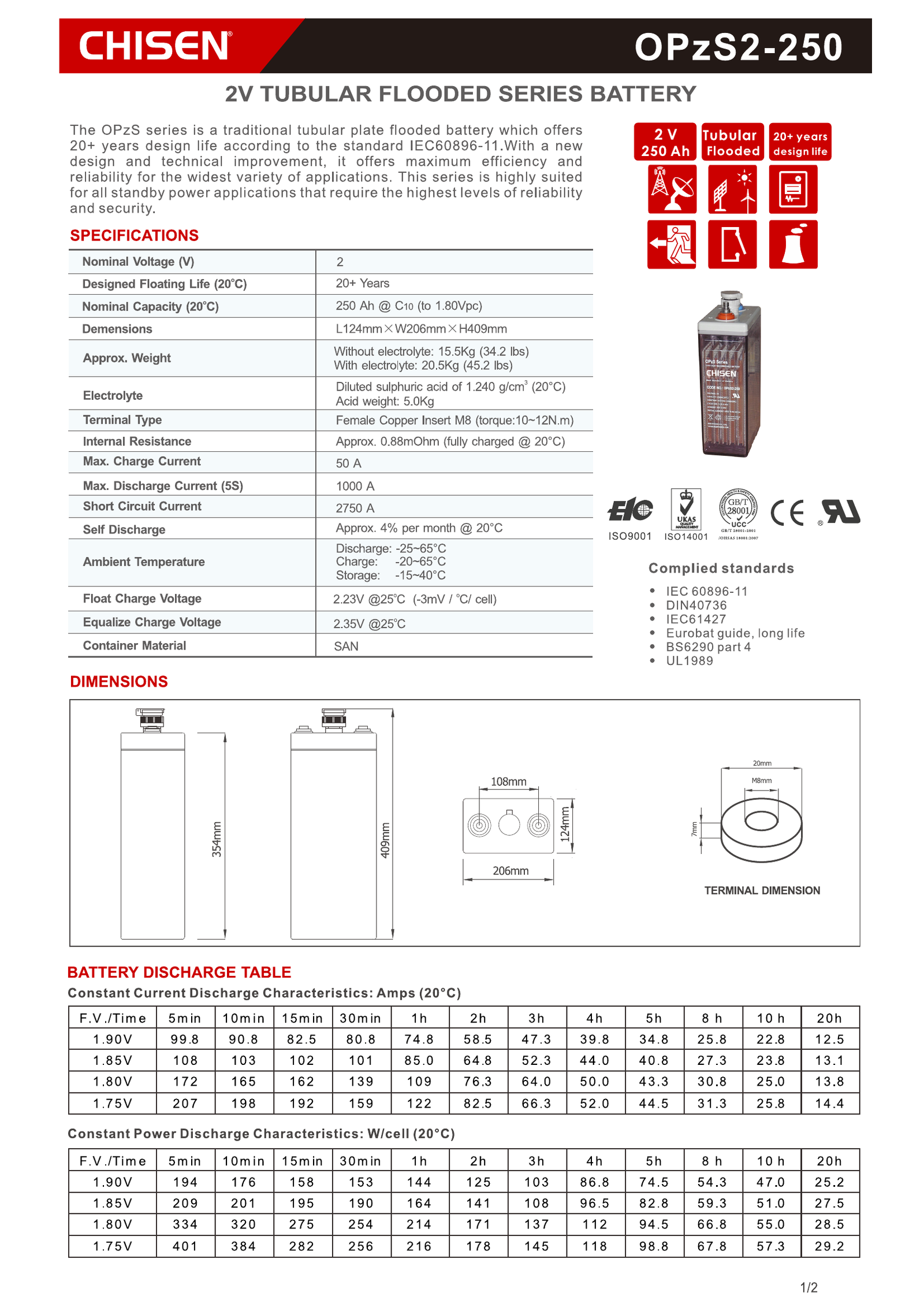
    OPzS2-250 (flooded)250 Ah15.5 kg / 20.5 kg124 × 206 × 354 mm409 mm50 A0.88 mΩ at 20 °C2750 A
    OPzS2-350 (flooded)350 Ah20.4 kg / 27.0 kg124 × 206 × 471 mm525 mm70 A0.62 mΩ at 20 °C3300 A
    OPzS2-420 (flooded)420 Ah24.0 kg / 32.0 kg145 × 206 × 471 mm525 mm84 A0.56 mΩ at 25 °C3500 A
    OPzV2-420 (gel)420 Ah31.5 kg (sealed)145 × 206 × 471 mm506 mm84 A0.62 mΩnot published

    Sources: OPzS2-250 and OPzS2-350 from their datasheets; OPzS2-420 and OPzV2-420 from their published specification pages and datasheets; the comparison itself is Arithmetic.

    Four numbers drive the decision. First, footprint and height. The 250 Ah cell is 124 × 206 × 354 mm with a 409 mm total height; the 350 Ah cell keeps the same 124 × 206 mm footprint but grows to 471 mm of body and 525 mm total height. The 420 Ah cell then steps the length up to 145 mm. A rack designed for the 350 Ah cell will not accept the 420 Ah cell without a new rail, and a room designed for a 409 mm cell will not accept a 525 mm cell without rebuilding the plinth.

    Second, weight. Dry weight rises from 15.5 kg to 20.4 kg and 24.0 kg; wet weight rises from 20.5 kg to 27.0 kg and 32.0 kg. At 350 Ah a cell that must be carried up a ladder or into a pit should be chosen with the 27.0 kg wet weight in mind, not the 20.4 kg dry one.

    Third, internal resistance. 0.88 mΩ at 250 Ah, 0.62 mΩ at 350 Ah and 0.56 mΩ at 420 Ah — so a 24-cell string of the 350 Ah cell presents 14.88 mΩ (24 × 0.62 mΩ, Arithmetic) against 21.12 mΩ for the 250 Ah cell (24 × 0.88 mΩ, Arithmetic) and 13.44 mΩ for the 420 Ah cell (24 × 0.56 mΩ, Arithmetic). The voltage drop under the same load falls as capacity rises, which matters when the string is long and the load is heavy.

    Fourth, the maintenance profile, and this is where the flooded-versus-sealed decision becomes concrete. The flooded OPzS2-350 carries 27.0 kg of electrolyte and 6.6 kg of acid per cell, so a 24-cell string carries 158.4 kg of acid (24 × 6.6 kg, Arithmetic) that must be topped up and eventually replaced. The gel OPzV2-420 carries the same 145 × 206 × 471 mm body at 31.5 kg with a 506 mm total height, needs no watering, and may be installed horizontally — at a higher internal resistance of 0.62 mΩ against 0.56 mΩ for the flooded cell of the same rating.

    48 V string arithmetic across the flooded range

    CellCells in stringNominal energyWeight with electrolyteWeight without electrolyteString internal resistanceMaximum charging current
    OPzS2-2502412,000 Wh492.0 kg372.0 kg21.12 mΩ1,200 A
    OPzS2-3502416,800 Wh648.0 kg489.6 kg14.88 mΩ1,680 A
    OPzS2-4202420,160 Wh768.0 kg576.0 kg13.44 mΩ2,016 A

    Source: Datasheet for the cell-level values, Arithmetic for the string rows.

    For a 54-cell 108 V substation string the OPzS2-350 arithmetic gives a float bus of 120.42 V (54 × 2.23 V), 37,800 Wh nominal, 1,458.0 kg with electrolyte (54 × 27.0 kg), 33.48 mΩ of internal resistance (54 × 0.62 mΩ) and a 3,780 A maximum charging current (54 × 70 A) (Arithmetic). On a 216 V three-phase DC bus the string becomes 108 cells, giving a float bus of 240.84 V (108 × 2.23 V), 75,600 Wh nominal and 2,916.0 kg with electrolyte (108 × 27.0 kg, Arithmetic).

    If your string is larger than 420 Ah per cell, move to the OPzS flooded range overview rather than scaling the numbers in this table proportionally — plate thickness, internal volume and electrolyte quantity change non-linearly with capacity. The OPzS2-500 2V500Ah cell is the next published step up, at 166 × 206 × 470 mm and 26.0 kg with electrolyte.

    §4 — The Framework: Seven Hard Checks Before You Sign

    Q1. Match the charger to the cell’s acceptance, not to the string. The maximum charging current of the OPzS2-350 is 70 A (Datasheet). A 24-cell string therefore accepts at most 1,680 A (24 × 70 A, Arithmetic). Most telecom float rectifiers are sized well below that, which is correct; a solar controller set to the array’s full output is where the limit gets breached.

    Q2. Apply temperature compensation to the setpoint, not to the battery. The published compensation is −3 mV/°C/cell on float (Datasheet), so a cell at 35 °C needs its 2.23 V/cell float reduced by 0.036 V. On a renewable site the published coefficient is −4 mV/cell/°C and the float setpoint is 2.25 ± 0.005 V/cell. Controllers that ignore this are permanently overcharging the string in the hot season and permanently undercharging it in winter.

    Q3. Design for the float life at the site’s real temperature. The 20+ year design figure is quoted at 20 °C (Datasheet). A cabinet in Chennai, on a roof in Lagos or an outdoor enclosure in Durban will not deliver that figure, and the honest way to plan a replacement interval is to take the 20 °C number and treat every 10 °C of ambient uplift as a materially shorter service life.

    Q4. Plan the watering interval from the real charging regime. A cell that is floated at 2.23 V/cell at 25 °C and never equalised loses water slowly; a cell that is equalised at 2.35 V/cell twice a month in a hot climate loses water fast enough to need attention on a monthly cycle. Put the interval in the maintenance contract, and put the electrolyte density check (1.240 g/cm³ at 20 °C, Datasheet) on the same schedule.

    Q5. Size the interconnects and torque them correctly. The terminal is a female copper insert M8 with a published torque of 10–12 N·m (Datasheet). Under-torqued terminals generate heat at the joint; over-torqued ones damage the insert. The 3300 A short-circuit current (Datasheet) determines how quickly the fault must be cleared, and the cable cross-section is set by the string current rather than by the bolt size.

    Q6. Decide how many strings run in parallel, and how they will be equalised. Two parallel strings will drift apart unless the charger has an equalising stage and the operator runs it. Parallel strings also multiply the water-top-up workload and the total string weight: 24 × 27.0 kg = 648.0 kg per 350 Ah string with electrolyte (Arithmetic), and 158.4 kg of acid per string (24 × 6.6 kg, Arithmetic).

    Q7. Confirm the standards the cell is built to. A 2 V vented cell for stationary duty is normally specified against IEC 60896-11 and the equivalent DIN 40736 envelope, with IEC 61427 for the renewable cycling test, the Eurobat long life guide, BS 6290 part 4 and UL 1989 for the North American market. CHISEN production runs under ISO 9001 and ISO 14001 with GB/T 28001 occupational health and safety management, and the range is supplied with CE documentation, so the paperwork trail should exist before the first container is booked.

    §5 — The Trust: What a Datasheet Must State — and What to Reject

    The single most useful question a buyer can ask a supplier is: “which document is this number from?” A published datasheet answers five questions that quotations never answer. What is the capacity rate and the end voltage? For the OPzS2-350 it is 350 Ah at C10 to 1.80 V/cell at 20 °C, and the full curve to 240 hours is published alongside it. What is the weight with and without electrolyte? 20.4 kg and 27.0 kg — both numbers, because a shipping weight quoted without electrolyte tells you nothing about handling. What is the total height over the terminals? 525 mm, not the 471 mm body height, and the difference is exactly the kind of detail that stops a cabinet from being delivered. What is the maximum charging current? 70 A. What is the reference temperature for the internal resistance and for the float life? 20 °C for both, and both references matter more than the numbers themselves.

    Against that standard, reject any quotation that quotes a float voltage above 2.23 V per cell for this model, or one that quotes a temperature compensation coefficient other than −3 mV/°C/cell, or one that quotes the 20+ year design life against 25 °C rather than 20 °C. The OPzS2-350 datasheet setpoints are 2.23 V/cell float, 2.35 V/cell equalising and −3 mV/°C/cell compensation, with the 20+ year design figure referenced to 20 °C. A supplier who quotes different numbers for the same model is either reading a different revision or inventing them.

    Two further quality signals are worth checking on site. First, ask for the plant audit trail: paste mixing, grid casting, group assembly, formation and sealing are the process steps that decide whether a 350 Ah cell really holds 350 Ah in year five, and they are the difference between a manufacturer and a packer. Second, ask for the certification package — ISO 9001, ISO 14001, CE, UL and IEC documentation should arrive with the quotation, not three weeks after the deposit. CHISEN runs eight production bases with roughly 70 million kVAh of annual capacity, and the company profile is published on the CHISEN company page.

    §6 — FAQ

    Q1. What is the rated capacity of the OPzS2-350 2V350Ah? 350 Ah at the 10-hour rate (35 A to 1.80 V/cell at 20 °C). The published table also gives 396 Ah at C24, 434 Ah at C48, 455 Ah at C72, 473 Ah at C100, 480 Ah at C120 and 490 Ah at C240 (Datasheet).

    Q2. How many cells does a 48 V string need, and how much energy does it hold? 24 cells. 48 V × 350 Ah = 16,800 Wh nominal (Arithmetic). The string weighs 648.0 kg with electrolyte (24 × 27.0 kg) and 489.6 kg dry (24 × 20.4 kg), and carries 158.4 kg of acid (24 × 6.6 kg).

    Q3. What float and equalising voltage should the charger use? Float 2.23 V/cell and equalising 2.35 V/cell, both referenced to 25 °C. On solar and wind sites use the higher 2.25 ± 0.005 V/cell float and 2.40 ± 0.01 V/cell equalising setpoint (Datasheet).

    Q4. What temperature compensation does the cell need? −3 mV/°C/cell on float (Datasheet), applied to the setpoint. At 35 °C the float setpoint falls by 0.036 V per cell. Renewable controllers use the published −4 mV/cell/°C coefficient.

    Q5. How long is the designed float life? 20+ years at 20 °C (Datasheet). Higher ambient temperatures reduce achievable service life, so site temperature has to be part of the replacement plan rather than a footnote.

    Q6. What is the maximum charging current? 70 A per cell, which is 0.20 × C10 (Datasheet). For a 24-cell string the theoretical ceiling is 1,680 A (24 × 70 A, Arithmetic), and the charger should normally deliver far less.

    Q7. Can this cell be installed without a permanent operator? It can be installed, but not forgotten. Flooded tubular cells need distilled-water top-up, electrolyte density checks, ventilation and periodic equalising. For an unmanned site, compare the published gel alternative instead.

    Q8. What is the internal resistance and short-circuit current? About 0.62 mΩ fully charged at 20 °C (Datasheet) and a 3300 A short-circuit current (Datasheet). The string resistance of a 24-cell arrangement is 14.88 mΩ (24 × 0.62 mΩ, Arithmetic), and the 3300 A figure is what your DC fuse and disconnection arrangement must be able to interrupt.

    Q9. How does the OPzS2-350 compare with the 250 Ah and 420 Ah cells? The 250 Ah cell is 124 × 206 × 354 mm with a 409 mm total height; the 350 Ah cell keeps the 124 × 206 mm footprint but grows to 471 mm of body and 525 mm total height; the 420 Ah cell steps the length up to 145 mm. Published differences are weight (20.4 kg dry and 27.0 kg wet against 15.5 kg and 20.5 kg for the 250 Ah cell, and 24.0 kg and 32.0 kg for the 420 Ah cell), charging limit (70 A against 50 A and 84 A), internal resistance (0.62 mΩ against 0.88 mΩ and 0.56 mΩ) and short-circuit current (3300 A against 2750 A and 3500 A). The OPzS2-350 2V350Ah model page carries the full data set.

    Q10. Which standards and certifications apply? The flooded 2 V stationary cell is built to the IEC 60896-11 and DIN 40736 envelope, with IEC 61427 for renewable cycling, the Eurobat long life guide, BS 6290 part 4 and UL 1989 for the North American market. CHISEN supplies the range with CE documentation under ISO 9001 and ISO 14001 management systems, with GB/T 28001 occupational health and safety certification.

    Expert Summary

    The OPzS2-350 2V350Ah is a 2 V flooded tubular vented lead-acid cell with a published 350 Ah capacity at the 10-hour rate (35 A to 1.80 V/cell at 20 °C), rising to 490 Ah at the 240-hour rate; float 2.23 V/cell and equalising 2.35 V/cell at 25 °C with −3 mV/°C/cell compensation and a 20+ year design float life referenced to 20 °C; a body of 124 × 206 × 471 mm with 525 mm total height over the terminals; a weight of 20.4 kg without electrolyte and 27.0 kg with electrolyte, of which 6.6 kg is acid; a 70 A maximum charging current; about 0.62 mΩ internal resistance at 20 °C; and a 3300 A short-circuit current. A 24-cell 48 V string holds 16,800 Wh nominal, weighs 648.0 kg with electrolyte and presents 14.88 mΩ of internal resistance; a 54-cell 108 V string floats at 120.42 V, holds 37,800 Wh and weighs 1,458.0 kg. The cell suits a manned telecom DC plant, substation or utility-scale storage container; where access is unattended, the published gel alternative trades a different internal resistance and installation orientation for the removal of the watering cycle.

    Contact CHISEN — 24-Hour Response

    If you are quoting a 2 V 350 Ah cell for a 48 V DC plant, a 108 V substation in Rotterdam or a storage container outside Nairobi, ask for the complete OPzS2-350 datasheet, the string layout drawing and the certification package, and ask for them in writing: email sales@chisen.cn, or message the export desk on WhatsApp at +86 131 6622 6999 (https://wa.me/8613166226999). One line describing your bus voltage, backup time and site temperature is enough for us to return the string arithmetic, the charger setpoints and the nearest capacity in the flooded range — or the gel equivalent if nobody will ever top up water on that site.

    Browse the full CHISEN lead-acid range and technical data at https://leadacidbattery.cn.

    Related CHISEN Product Pages

    • OPzS2-350 2V350Ah model page — full published specification set
    • OPzS2-420 2V420Ah tubular flooded cell — the next capacity step, 420 Ah
    • Tubular flooded battery range — 2 V cells from 100 Ah to 3,000 Ah

    Related CHISEN Buyer Guides

  • pg 1 9

    OPzS2-150 2V150Ah Flooded Tubular Cell: Published Specs and Sizing

    Answer First

    The OPzS2-150 2V150Ah is a 2 V, 150 amp-hour flooded tubular vented lead-acid cell rated at the 10-hour rate — 15 A for 10 hours down to 1.80 V per cell at 20 °C — and it is the correct cell for a telecom DC plant, a substation or a solar-powered cabinet that needs a 48 V bus holding about 7.2 kWh nominal per string, on a site where somebody will still read the electrolyte level and top up distilled water every quarter.

    It is not a sealed block. Hydrogen venting, acid-proof flame-retardant vent plugs, scheduled water top-up and periodic equalisation are part of the product, not optional extras, and a project that treats the OPzS2-150 2V150Ah as a drop-in sealed cabinet battery discovers the difference in the first hot season.

    The complete published data set for this cell sits on the OPzS2-150 2V150Ah model page, and the rest of the flooded range is listed under tubular flooded lead-acid batteries.

    Key Takeaways

    • Capacity is rate-dependent. The nameplate figure is 150 Ah at C10 (15 A to 1.80 V/cell at 20 °C). At longer rates the cell delivers more: 170 Ah at C24, 186 Ah at C48, 195 Ah at C72, 203 Ah at C100, 206 Ah at C120 and 210 Ah at C240 (Datasheet).
    • Charging setpoints are fixed by the datasheet. Float 2.23 V/cell at 25 °C, equalising 2.35 V/cell at 25 °C, temperature compensation −3 mV/°C/cell, designed float life 20+ years at 20 °C (Datasheet). Solar and wind controllers use the 2.25 ± 0.005 V/cell float and 2.40 ± 0.01 V/cell equalising setpoints, with a −4 mV/cell/°C compensation coefficient (Datasheet).
    • Mechanical data is what decides the rack. Body 103 × 206 × 354 mm, 409 mm total height over the terminals, 10.5 kg without electrolyte and 14.5 kg with electrolyte (Datasheet).
    • Two limits protect the cell. Maximum charging current is 30 A (0.20 × C10) and internal resistance is about 1.2 mΩ fully charged at 20 °C, with a 2400 A short-circuit current (Datasheet).
    • A 48 V string is simple arithmetic. 24 cells give 7,200 Wh nominal, 348.0 kg with electrolyte (24 × 14.5 kg) and 28.8 mΩ of internal resistance (24 × 1.2 mΩ) (Arithmetic).

    §1 — OPzS2-150 2V150Ah Quick Specifications

    ParameterOPzS2-150 published valueSource
    ModelOPzS2-150, flooded tubular stationary cell, 2 V 150 AhModel page
    Nominal voltage2 VDatasheet
    Nominal capacity150 Ah at C10 (15 A, 1.80 V/cell, 20 °C)Datasheet
    C10 discharge current15 A (150 Ah ÷ 10 h)Arithmetic
    Capacity at C24 / C48 / C72170 Ah / 186 Ah / 195 AhDatasheet
    Capacity at C100 / C120 / C240203 Ah / 206 Ah / 210 AhDatasheet
    Float voltage2.23 V/cell at 25 °CDatasheet
    Equalising voltage2.35 V/cell at 25 °CDatasheet
    Float setpoint, solar and wind2.25 ± 0.005 V/cell at 25 °CDatasheet
    Equalising setpoint, solar and wind2.40 ± 0.01 V/cell at 25 °CDatasheet
    Temperature compensation, float−3 mV/°C/cellDatasheet
    Temperature compensation, solar and wind−4 mV/cell/°CDatasheet
    Designed float life20+ years at 20 °CDatasheet
    Dimensions L × W × H103 × 206 × 354 mmDatasheet
    Container height354 mmDatasheet
    Total height over terminals409 mmDatasheet
    Terminal centre spacing108 mmDatasheet
    Terminal20 mm OD, M8 thread, 7 mm depth, female copper insert M8Datasheet
    Terminal tightening torque10–12 N·mDatasheet
    Weight without electrolyte10.5 kg (23.2 lbs)Datasheet
    Weight with electrolyte14.5 kg (32.0 lbs)Datasheet
    ElectrolyteDiluted sulphuric acid, 1.240 g/cm³ at 20 °CDatasheet
    Acid weight per cell4.0 kgDatasheet
    Internal resistanceApprox. 1.2 mΩ, fully charged at 20 °CDatasheet
    Maximum charge current30 ADatasheet
    Charge characteristicConstant charge at 0.15 CA to 2.40 V at 20 °CDatasheet
    Maximum discharge current (5 s)1000 ADatasheet
    Short circuit current2400 ADatasheet
    Self dischargeApprox. 4 % per month at 20 °CDatasheet
    Ambient, discharge−25 °C to +65 °CDatasheet
    Ambient, charge−20 °C to +65 °CDatasheet
    Ambient, storage−15 °C to +40 °CDatasheet
    Complied standardsIEC 60896-11, DIN 40736, IEC 61427, Eurobat long life guide, BS 6290 part 4, UL 1989Datasheet
    Management systems and marksISO 9001, ISO 14001, GB/T 28001, CE, RU recognised componentDatasheet

    Every row above is traceable. Values taken from the manufacturer’s OPzS2-150 datasheet are marked Datasheet, values taken from the published English product page are marked Model page, and derived figures are marked Arithmetic wherever they appear in the text. If a supplier cannot tell you which of the three a given figure is, treat the figure as unverified.

    Solar and wind controller setpoints for the OPzS2-150

    The same datasheet publishes a separate parameter set for renewable sites, and these are the values that actually go into a solar or wind charge controller.

    Controller parameterPublished settingWhy the number matters
    Over voltage disconnect2.47 ± 0.01 V/cell at 25 °CThe point at which the controller stops charging and the array is isolated
    Regulation / equalising voltage2.40 ± 0.01 V/cell at 25 °CHigher than the mains float because the array has to push against the bus
    Array reconnection voltage2.23 ± 0.005 V/cell at 25 °CThe bus voltage at which charging resumes
    Float voltage setting2.25 ± 0.005 V/cell at 25 °CThe renewable float setpoint, above the 2.23 V mains float
    Low voltage alarm1.95 ± 0.005 V/cell at 25 °CThe alarm threshold for the control room
    Low voltage disconnect1.90 ± 0.005 V/cell at 25 °CThe load is shed at this point to protect the cells
    Load reconnect voltage2.09 ± 0.01 V/cell at 25 °CThe load is restored once the bus recovers
    Temperature compensation coefficient−4 mV/cell/°CThe coefficient used on renewable sites, distinct from the −3 mV/°C/cell float value

    Long-time discharge capacity for solar and wind duty (final voltage 1.85 V)

    Discharge rateC24C48C72C100C120C240
    OPzS2-150 capacity170 Ah186 Ah195 Ah203 Ah206 Ah210 Ah
    Stored energy at 2 V340 Wh372 Wh390 Wh406 Wh412 Wh420 Wh

    Source: Datasheet for the capacity row, Arithmetic for the energy row (2 V × Ah).

    §2 — The Pain: Where 2V 150Ah Projects Go Wrong

    The first failure is a specification failure. Buyers routinely receive a quotation that says only “2V 150Ah tubular” and treat every 2 V 150 Ah cell in the world as interchangeable. The published OPzS2-150 data makes the differences explicit: capacity at C10 is 150 Ah, but capacity at C24 is 170 Ah and at C240 is 210 Ah. A bank sized on the C10 number for a slow-discharge backup duty is undersized; a bank sized on the C240 number for a five-hour discharge duty is over-purchased. Both mistakes trace back to a quotation that never stated the rate and the end voltage.

    The second failure is thermal. A 48 V string of 24 OPzS2-150 cells accepts a maximum charging current of 30 A per cell, so a charger set to deliver more — which happens when the charger is sized for the string’s nominal power rather than for the cells’ acceptance — pushes the electrolyte into gassing and dries the separator faster than the topping-up interval can repair. The same string on a solar site needs the higher 2.25 ± 0.005 V/cell float and the 2.40 ± 0.01 V/cell equalising setpoint; on a mains-float site the correct values are 2.23 V/cell and 2.35 V/cell at 25 °C. These are not interchangeable, and a controller left on the wrong setpoint is the classic cause of premature capacity loss.

    The third failure is weight and access planning. The OPzS2-150 is 10.5 kg without electrolyte and 14.5 kg with electrolyte, and the full height over the terminals is 409 mm, not the 354 mm body height. A 24-cell string with electrolyte weighs 348.0 kg (24 × 14.5 kg, Arithmetic). Cabinets, plinths and lifting plans are usually drawn against the body height and a lighter shipping weight, and the result is a string that does not fit the rack and a handling plan that understates the load.

    The fourth failure is assuming sealed behaviour. This cell vents hydrogen during overcharge, needs acid-proof flame-retardant vent plugs, needs distilled water, and needs a scheduled equalising period. Those four obligations are why the OPzS2-150 2V150Ah wins in cabinets with a permanent operator — a central DC plant serving a national mobile network operator in Chennai, a fixed-line exchange in Rotterdam, a substation compound outside Nairobi — and loses in unmanned roadside or container sites.

    The fifth failure, and the one that costs the most money, is ignoring what happens when two strings in parallel drift apart. A 24-cell string of OPzS2-150 cells presents 28.8 mΩ of internal resistance (24 × 1.2 mΩ, Arithmetic). Two strings in parallel do not share load evenly once their float voltages separate by a few millivolts, and the weaker string silently carries less current while ageing faster. The cure is an equalising stage plus a rotation discipline, and both belong in the maintenance contract rather than in a commissioning checklist.

    Markets also shape the delivery plan. A lead-acid article of this class leaves through Hamburg, Santos and Singapore for importers in Europe, Brazil and South-East Asia, and the import file has to name the destination market before the container is booked, because a vented cell and a sealed cell do not clear every port under the same rules.

    §3 — The Choice: The OPzS2-150 Against Its Published Siblings

    Buyers comparing cells inside the 100 Ah to 200 Ah window are usually choosing between a flooded cell and a gel cell, or between three flooded capacities. The table below uses published values only.

    ModelCapacity at C10Weight dry / with electrolyteDimensions L × W × HTotal heightMax charging currentInternal resistanceShort-circuit current
    OPzS2-100100 Ah8.0 kg / 12.6 kg103 × 206 × 354 mm409 mm20 A1.0 mΩ at 20 °C1500 A
    OPzS2-150150 Ah10.5 kg / 14.5 kg103 × 206 × 354 mm409 mm30 A1.2 mΩ at 20 °C2400 A
    OPzS2-200200 Ah13.0 kg / 17.5 kg103 × 206 × 354 mm409 mm40 A0.95 mΩ at 20 °C2600 A
    OPzV2-100 (gel)100 Ah13.2 kg (sealed)103 × 206 × 354 mm390 mm30 A1.1 mΩnot published

    Sources: OPzS2-100 and OPzS2-200 from their datasheets, with the OPzS2-100 short-circuit current from its model page; OPzV2-100 from the model page and its datasheet; the comparison itself is Arithmetic.

    Four numbers drive the decision. First, dry weight: 8.0 kg, 10.5 kg and 13.0 kg for the three flooded cells — a cell that must be carried up a ladder or into a pit should be chosen with the wet weight in mind, not the dry one. Second, the charging current limit of 20 A, 30 A and 40 A, which must be matched to the charger output. Third, internal resistance, which does not fall in a straight line with capacity — 1.0 mΩ at 100 Ah, 1.2 mΩ at 150 Ah and 0.95 mΩ at 200 Ah — so a 24-cell string of the 200 Ah cell presents 22.8 mΩ (24 × 0.95 mΩ, Arithmetic) against 28.8 mΩ for the 150 Ah cell (24 × 1.2 mΩ, Arithmetic) and 24.0 mΩ for the 100 Ah cell (24 × 1.0 mΩ, Arithmetic). The 150 Ah cell therefore has the highest voltage drop of the three under the same load, which matters when the string is long and the load is heavy.

    The fourth number is the maintenance profile, and here the published data is unambiguous. The flooded OPzS2-150 carries 14.5 kg of electrolyte in an open container that must be topped up and periodically equalised. The gel OPzV2-100 carries the same 103 × 206 mm footprint with a 390 mm total height, weighs 13.2 kg with the electrolyte immobilised in the gel, and needs no watering — the price of that is a 1.1 mΩ internal resistance, a 30 A charging limit and a shorter life under deep cycling. For a manned substation with a technician on call, the flooded cell usually delivers the lower cost per usable year; for a sealed container with no access, the gel cell removes a whole maintenance category. Both routes are legitimate, and the published figures above are what the comparison should be built on.

    48 V string arithmetic across the three flooded capacities

    CellCells in stringNominal energyWeight with electrolyteWeight without electrolyteString internal resistanceMaximum charging current
    OPzS2-100244,800 Wh302.4 kg192.0 kg24.0 mΩ480 A
    OPzS2-150247,200 Wh348.0 kg252.0 kg28.8 mΩ720 A
    OPzS2-200249,600 Wh420.0 kg312.0 kg22.8 mΩ960 A

    Source: Datasheet for the cell-level values, Arithmetic for the string rows.

    For a 54-cell 108 V substation string the same OPzS2-150 arithmetic gives a float bus of 120.42 V (54 × 2.23 V), 16,200 Wh nominal, 783.0 kg with electrolyte (54 × 14.5 kg), 64.8 mΩ of internal resistance (54 × 1.2 mΩ) and a 1,620 A maximum charging current (54 × 30 A) (Arithmetic).

    The same discipline applies further up the size range. If your string is larger than 200 Ah per cell, move to the OPzS flooded range overview rather than scaling the numbers in this table proportionally — plate thickness, internal volume and electrolyte quantity change non-linearly with capacity. The OPzS2-500 2V500Ah cell is the next published step up, at 166 × 206 × 470 mm and 26.0 kg with electrolyte.

    §4 — The Framework: Seven Hard Checks Before You Sign

    Q1. Match the charger to the cell’s acceptance, not to the string. The maximum charging current of the OPzS2-150 is 30 A (Datasheet). A 24-cell string therefore accepts at most 720 A (24 × 30 A, Arithmetic). Most telecom float rectifiers are sized well below that, which is correct; a solar controller set to the array’s full output is where the limit gets breached.

    Q2. Apply temperature compensation to the setpoint, not to the battery. The published compensation is −3 mV/°C/cell on float (Datasheet), so a cell at 35 °C needs its 2.23 V/cell float reduced by 0.036 V. On a renewable site the published coefficient is −4 mV/cell/°C and the float setpoint is 2.25 ± 0.005 V/cell. Controllers that ignore this are permanently overcharging the string in the hot season and permanently undercharging it in winter.

    Q3. Design for the float life at the site’s real temperature. The 20+ year design figure is quoted at 20 °C (Datasheet). A cabinet in Chennai, on a roof in Lagos or an outdoor enclosure in Durban will not deliver that figure, and the honest way to plan a replacement interval is to take the 20 °C number and treat every 10 °C of ambient uplift as a materially shorter service life. Projects that publish a 20-year asset life for a string sitting in a 35 °C room have not done the arithmetic.

    Q4. Plan the watering interval from the real charging regime. A cell that is floated at 2.23 V/cell at 25 °C and never equalised loses water slowly; a cell that is equalised at 2.35 V/cell twice a month in a hot climate loses water fast enough to need attention on a monthly cycle. Put the interval in the maintenance contract, and put the electrolyte density check (1.240 g/cm³ at 20 °C, Datasheet) on the same schedule. Each cell in the OPzS2-150 holds 4.0 kg of acid, so a 24-cell string carries 96.0 kg of electrolyte (24 × 4.0 kg, Arithmetic) that has to be topped up and eventually replaced.

    Q5. Size the interconnects and torque them correctly. The terminal is a copper female insert M8 with a published torque of 10–12 N·m (Datasheet). Under-torqued terminals generate heat at the joint; over-torqued ones damage the insert. For a 24-cell string the interconnect carries the full string current, so the cable cross-section is set by that current and the 2400 A short-circuit current (Datasheet) determines how quickly the fault must be cleared.

    Q6. Decide how many strings run in parallel, and how they will be equalised. Two parallel strings of 12 cells in series each will drift apart unless the charger has an equalising stage and the operator runs it. Parallel strings also multiply the water-top-up workload and the total string weight: 24 × 14.5 kg = 348.0 kg per 150 Ah string with electrolyte (Arithmetic).

    Q7. Confirm the standards the cell is built to. A 2 V vented cell for stationary duty is normally specified against IEC 60896-11 and the equivalent DIN 40736 envelope, with IEC 61427 for the renewable cycling test, the Eurobat long life guide, BS 6290 part 4 and UL 1989 for the North American market. CHISEN production runs under ISO 9001 and ISO 14001 with GB/T 28001 occupational health and safety management, and the range is supplied with CE documentation, so the paperwork trail should exist before the first container is booked.

    §5 — The Trust: What a Datasheet Must State — and What to Reject

    The single most useful question a buyer can ask a supplier is: “which document is this number from?” A published datasheet answers five questions that quotations never answer. What is the capacity rate and the end voltage? For the OPzS2-150 it is 150 Ah at C10 to 1.80 V/cell at 20 °C, and the full curve to 240 hours is published alongside it. What is the weight with and without electrolyte? 10.5 kg and 14.5 kg — both numbers, because a shipping weight quoted without electrolyte tells you nothing about handling. What is the total height over the terminals? 409 mm, not the 354 mm body height, and the difference is exactly the kind of detail that stops a cabinet from being delivered. What is the maximum charging current? 30 A. What is the reference temperature for the internal resistance and for the float life? 20 °C for both, and both references matter more than the numbers themselves.

    Against that standard, reject any quotation that quotes a float voltage above 2.23 V per cell for this model, or one that quotes a temperature compensation coefficient other than −3 mV/°C/cell, or one that quotes the 20+ year design life against 25 °C rather than 20 °C. The OPzS2-150 datasheet setpoints are 2.23 V/cell float, 2.35 V/cell equalising and −3 mV/°C/cell compensation, with the 20+ year design figure referenced to 20 °C. A supplier who quotes different numbers for the same model is either reading a different revision or inventing them.

    Two further quality signals are worth checking on site. First, ask for the plant audit trail: paste mixing, grid casting, group assembly, formation and sealing are the process steps that decide whether a 150 Ah cell really holds 150 Ah in year five, and they are the difference between a manufacturer and a packer. Second, ask for the certification package — ISO 9001, ISO 14001, CE, UL and IEC documentation should arrive with the quotation, not three weeks after the deposit. CHISEN runs eight production bases with roughly 70 million kVAh of annual capacity, and the company profile is published on the CHISEN company page if you want to check the manufacturing scale behind a quotation before you commit a container.

    §6 — FAQ

    Q1. What is the rated capacity of the OPzS2-150 2V150Ah? 150 Ah at the 10-hour rate (15 A to 1.80 V/cell at 20 °C). The published table also gives 170 Ah at C24, 186 Ah at C48, 195 Ah at C72, 203 Ah at C100, 206 Ah at C120 and 210 Ah at C240 (Datasheet).

    Q2. How many cells does a 48 V string need, and how much energy does it hold? 24 cells. 48 V × 150 Ah = 7,200 Wh nominal (Arithmetic). The string weighs 348.0 kg with electrolyte (24 × 14.5 kg) and 252.0 kg dry (24 × 10.5 kg), and carries 96.0 kg of acid (24 × 4.0 kg).

    Q3. What float and equalising voltage should the charger use? Float 2.23 V/cell and equalising 2.35 V/cell, both referenced to 25 °C. On solar and wind sites use the higher 2.25 ± 0.005 V/cell float and 2.40 ± 0.01 V/cell equalising setpoint (Datasheet).

    Q4. What temperature compensation does the cell need? −3 mV/°C/cell on float (Datasheet), applied to the setpoint. At 35 °C the float setpoint falls by 0.036 V per cell. Renewable controllers use the published −4 mV/cell/°C coefficient.

    Q5. How long is the designed float life? 20+ years at 20 °C (Datasheet). Higher ambient temperatures reduce achievable service life, so site temperature has to be part of the replacement plan rather than a footnote.

    Q6. What is the maximum charging current? 30 A per cell, which is 0.20 × C10 (Datasheet). For a 24-cell string the theoretical ceiling is 720 A (24 × 30 A, Arithmetic), and the charger should normally deliver far less.

    Q7. Can this cell be installed without a permanent operator? It can be installed, but not forgotten. Flooded tubular cells need distilled-water top-up, electrolyte density checks, ventilation and periodic equalising. For an unmanned site, compare the published gel alternative instead.

    Q8. What is the internal resistance and short-circuit current? About 1.2 mΩ fully charged at 20 °C (Datasheet) and a 2400 A short-circuit current (Datasheet). The string resistance of a 24-cell arrangement is 28.8 mΩ (24 × 1.2 mΩ, Arithmetic), and the 2400 A figure is what your DC fuse and disconnection arrangement must be able to interrupt.

    Q9. How does the OPzS2-150 compare with the 100 Ah and 200 Ah cells? Same 103 × 206 mm footprint and the same 409 mm total height. The published differences are weight (10.5 kg dry and 14.5 kg wet against 8.0 kg and 12.6 kg for the 100 Ah cell, and 13.0 kg and 17.5 kg for the 200 Ah cell), charging limit (30 A against 20 A and 40 A), internal resistance (1.2 mΩ against 1.0 mΩ and 0.95 mΩ) and short-circuit current (2400 A against 1500 A and 2600 A). The OPzS2-150 2V150Ah model page carries the full data set.

    Q10. Which standards and certifications apply? The flooded 2 V stationary cell is built to the IEC 60896-11 and DIN 40736 envelope, with IEC 61427 for renewable cycling, the Eurobat long life guide, BS 6290 part 4 and UL 1989 for the North American market. CHISEN supplies the range with CE documentation under ISO 9001 and ISO 14001 management systems, with GB/T 28001 occupational health and safety certification.

    Expert Summary

    The OPzS2-150 2V150Ah is a 2 V flooded tubular vented lead-acid cell with a published 150 Ah capacity at the 10-hour rate (15 A to 1.80 V/cell at 20 °C), rising to 210 Ah at the 240-hour rate; float 2.23 V/cell and equalising 2.35 V/cell at 25 °C with −3 mV/°C/cell compensation and a 20+ year design float life referenced to 20 °C; a body of 103 × 206 × 354 mm with 409 mm total height over the terminals; a weight of 10.5 kg without electrolyte and 14.5 kg with electrolyte, of which 4.0 kg is acid; a 30 A maximum charging current; about 1.2 mΩ internal resistance at 20 °C; and a 2400 A short-circuit current. A 24-cell 48 V string of these cells holds 7,200 Wh nominal, weighs 348.0 kg with electrolyte and presents 28.8 mΩ of internal resistance. The cell is the correct choice where a manned telecom DC plant, substation or renewable cabinet benefits from long float life and low cost per usable year; where site access is unattended, the published gel alternative trades a slightly different internal resistance and charging limit for the removal of the watering cycle.

    Contact CHISEN — 24-Hour Response

    If you are quoting a 2 V 150 Ah cell for a 48 V DC plant, a substation in Rotterdam or a solar cabinet outside Nairobi, ask for the complete OPzS2-150 datasheet, the string layout drawing and the certification package, and ask for them in writing: email sales@chisen.cn, or message the export desk on WhatsApp at +86 131 6622 6999 (https://wa.me/8613166226999). One line describing your bus voltage, backup time and site temperature is enough for us to return the string arithmetic, the charger setpoints and the nearest capacity in the flooded range — or the gel equivalent if nobody will ever top up water on that site.

    Browse the full CHISEN lead-acid range and technical data at https://leadacidbattery.cn.

    Related CHISEN Product Pages

    • OPzS2-150 2V150Ah model page — full published specification set
    • OPzS2-200 2V200Ah tubular flooded cell — the next capacity step, 200 Ah
    • Tubular flooded battery range — 2 V cells from 100 Ah to 3,000 Ah

    Related CHISEN Buyer Guides

  • pg 1 8

    OPzS2-250 2V250Ah Flooded Tubular Cell: Specs and String Sizing

    Answer First

    The OPzS2-250 2V250Ah is a 2 V, 250 amp-hour flooded tubular vented lead-acid cell rated at the 10-hour rate — 25 A for 10 hours down to 1.80 V per cell at 20 °C — and it is the right cell for a telecom DC plant, a 108 V substation bus or a solar-and-storage cabinet that needs roughly 12 kWh nominal per 48 V string, on a site where a technician will still read the electrolyte level and top up distilled water every quarter.

    It is not a sealed block. Hydrogen venting, acid-proof flame-retardant vent plugs, scheduled water top-up and periodic equalisation are part of the product, not optional extras. A project that treats the OPzS2-250 2V250Ah as a drop-in sealed cabinet battery discovers the difference in the first hot season.

    The complete published data set sits on the OPzS2-250 2V250Ah model page, and the rest of the flooded range is listed under tubular flooded lead-acid batteries.

    Key Takeaways

    • Capacity is rate-dependent. The nameplate figure is 250 Ah at C10 (25 A to 1.80 V/cell at 20 °C). At longer rates the cell delivers more: 283 Ah at C24, 310 Ah at C48, 325 Ah at C72, 338 Ah at C100, 343 Ah at C120 and 350 Ah at C240 (Datasheet).
    • Charging setpoints are fixed by the datasheet. Float 2.23 V/cell at 25 °C, equalising 2.35 V/cell at 25 °C, temperature compensation −3 mV/°C/cell, designed float life 20+ years at 20 °C (Datasheet). Solar and wind controllers use the 2.25 ± 0.005 V/cell float and 2.40 ± 0.01 V/cell equalising setpoints (Datasheet).
    • Mechanical data is what decides the rack. Body 124 × 206 × 354 mm, 409 mm total height over the terminals, 15.5 kg without electrolyte and 20.5 kg with electrolyte, of which 5.0 kg is acid (Datasheet).
    • Two limits protect the cell. Maximum charging current is 50 A (0.20 × C10) and internal resistance is about 0.88 mΩ fully charged at 20 °C, with a 2750 A short-circuit current (Datasheet).
    • A 48 V string is simple arithmetic. 24 cells give 12,000 Wh nominal, 492.0 kg with electrolyte (24 × 20.5 kg) and 21.12 mΩ of internal resistance (24 × 0.88 mΩ) (Arithmetic).

    §1 — OPzS2-250 2V250Ah Quick Specifications

    ParameterOPzS2-250 published valueSource
    ModelOPzS2-250, flooded tubular stationary cell, 2 V 250 AhModel page
    Nominal voltage2 VDatasheet
    Nominal capacity250 Ah at C10 (25 A, 1.80 V/cell, 20 °C)Datasheet
    C10 discharge current25 A (250 Ah ÷ 10 h)Arithmetic
    Capacity at C24 / C48 / C72283 Ah / 310 Ah / 325 AhDatasheet
    Capacity at C100 / C120 / C240338 Ah / 343 Ah / 350 AhDatasheet
    Float voltage2.23 V/cell at 25 °CDatasheet
    Equalising voltage2.35 V/cell at 25 °CDatasheet
    Float setpoint, solar and wind2.25 ± 0.005 V/cell at 25 °CDatasheet
    Equalising setpoint, solar and wind2.40 ± 0.01 V/cell at 25 °CDatasheet
    Temperature compensation, float−3 mV/°C/cellDatasheet
    Temperature compensation, solar and wind−4 mV/cell/°CDatasheet
    Designed float life20+ years at 20 °CDatasheet
    Dimensions L × W × H124 × 206 × 354 mmDatasheet
    Container height354 mmDatasheet
    Total height over terminals409 mmDatasheet
    Terminal centre spacing108 mmDatasheet
    TerminalFemale copper insert M8, torque 10–12 N·mDatasheet
    Weight without electrolyte15.5 kg (34.2 lbs)Datasheet
    Weight with electrolyte20.5 kg (45.2 lbs)Datasheet
    ElectrolyteDiluted sulphuric acid, 1.240 g/cm³ at 20 °CDatasheet
    Acid weight per cell5.0 kgDatasheet
    Internal resistanceApprox. 0.88 mΩ, fully charged at 20 °CDatasheet
    Maximum charge current50 ADatasheet
    Charge characteristicConstant charge at 0.15 CA to 2.40 V at 20 °CDatasheet
    Maximum discharge current (5 s)1000 ADatasheet
    Short circuit current2750 ADatasheet
    Self dischargeApprox. 4 % per month at 20 °CDatasheet
    Ambient, discharge−25 °C to +65 °CDatasheet
    Ambient, charge−20 °C to +65 °CDatasheet
    Ambient, storage−15 °C to +40 °CDatasheet
    Complied standardsIEC 60896-11, DIN 40736, IEC 61427, Eurobat long life guide, BS 6290 part 4, UL 1989Datasheet
    Management systems and marksISO 9001, ISO 14001, GB/T 28001, CE, RU recognised componentDatasheet

    Every row above is traceable. Values taken from the manufacturer’s OPzS2-250 datasheet are marked Datasheet, values taken from the published English product page are marked Model page, and derived figures are marked Arithmetic wherever they appear in the text. A supplier who cannot tell you which of the three a given figure is has not verified it.

    Solar and wind controller setpoints for the OPzS2-250

    Controller parameterPublished settingWhy the number matters
    Over voltage disconnect2.47 ± 0.01 V/cell at 25 °CThe point at which the controller stops charging and the array is isolated
    Regulation / equalising voltage2.40 ± 0.01 V/cell at 25 °CHigher than the mains float because the array has to push against the bus
    Array reconnection voltage2.23 ± 0.005 V/cell at 25 °CThe bus voltage at which charging resumes
    Float voltage setting2.25 ± 0.005 V/cell at 25 °CThe renewable float setpoint, above the 2.23 V mains float
    Low voltage alarm1.95 ± 0.005 V/cell at 25 °CThe alarm threshold for the control room
    Low voltage disconnect1.90 ± 0.005 V/cell at 25 °CThe load is shed at this point to protect the cells
    Load reconnect voltage2.09 ± 0.01 V/cell at 25 °CThe load is restored once the bus recovers
    Temperature compensation coefficient−4 mV/cell/°CThe coefficient used on renewable sites, distinct from the −3 mV/°C/cell float value

    Long-time discharge capacity for solar and wind duty (final voltage 1.85 V)

    Discharge rateC24C48C72C100C120C240
    OPzS2-250 capacity283 Ah310 Ah325 Ah338 Ah343 Ah350 Ah
    Stored energy at 2 V566 Wh620 Wh650 Wh676 Wh686 Wh700 Wh

    Source: Datasheet for the capacity row, Arithmetic for the energy row (2 V × Ah).

    §2 — The Pain: Where 2V 250Ah Projects Go Wrong

    The first failure is a specification failure. Buyers routinely receive a quotation that says only “2V 250Ah tubular” and treat every 2 V 250 Ah cell in the world as interchangeable. The published OPzS2-250 data makes the differences explicit: capacity at C10 is 250 Ah, but capacity at C24 is 283 Ah and at C240 is 350 Ah. A bank sized on the C10 number for a slow-discharge backup duty is undersized; a bank sized on the C240 number for a five-hour discharge duty is over-purchased. Both mistakes trace back to a quotation that never stated the rate and the end voltage.

    The second failure is thermal. A 48 V string of 24 OPzS2-250 cells accepts a maximum charging current of 50 A per cell, so a charger set to deliver more — which happens when the charger is sized for the string’s nominal power rather than for the cells’ acceptance — pushes the electrolyte into gassing and dries the separator faster than the topping-up interval can repair. The same string on a solar site needs the higher 2.25 ± 0.005 V/cell float and the 2.40 ± 0.01 V/cell equalising setpoint; on a mains-float site the correct values are 2.23 V/cell and 2.35 V/cell at 25 °C. A controller left on the wrong setpoint is the classic cause of premature capacity loss.

    The third failure is weight and access planning. The OPzS2-250 is 15.5 kg without electrolyte and 20.5 kg with electrolyte, and the full height over the terminals is 409 mm, not the 354 mm body height. A 24-cell string with electrolyte weighs 492.0 kg (24 × 20.5 kg, Arithmetic), and a 54-cell 108 V string weighs 1,107.0 kg (54 × 20.5 kg, Arithmetic). Cabinets, plinths, floor loading and lifting plans are usually drawn against the body height and a lighter shipping weight, and the result is a string that does not fit the rack and a handling plan that understates the load.

    The fourth failure is assuming sealed behaviour. This cell vents hydrogen during overcharge, needs acid-proof flame-retardant vent plugs, needs distilled water, and needs a scheduled equalising period. Those four obligations are why the OPzS2-250 2V250Ah wins in cabinets with a permanent operator — a central DC plant serving a national mobile network operator in Chennai, a fixed-line exchange in Rotterdam, a substation compound outside Nairobi — and loses in unmanned roadside or container sites.

    The fifth failure is ignoring parallel strings. A 48 V string of OPzS2-250 cells presents 21.12 mΩ of internal resistance (24 × 0.88 mΩ, Arithmetic). Two strings in parallel do not share load evenly once their float voltages separate by a few millivolts, and the weaker string silently carries less current while ageing faster. The cure is an equalising stage plus a rotation discipline, and both belong in the maintenance contract rather than in a commissioning checklist.

    The delivery plan is part of the specification too. A 2 V 250 Ah vented article like this one leaves through Karachi and Santos for buyers in Pakistan and Brazil, and for importers moving stock through Mumbai, and the import file has to name the destination market before the container is booked rather than after it has sailed.

    §3 — The Choice: The OPzS2-250 Against Its Published Siblings

    Buyers comparing cells between 150 Ah and 350 Ah are choosing between three flooded capacities or between a flooded cell and a sealed one. The table below uses published values only.

    ModelCapacity at C10Weight dry / with electrolyteDimensions L × W × HTotal heightMax charging currentInternal resistanceShort-circuit current
    OPzS2-150150 Ah10.5 kg / 14.5 kg103 × 206 × 354 mm409 mm30 A1.2 mΩ at 20 °C2400 A
    OPzS2-200200 Ah13.0 kg / 17.5 kg103 × 206 × 354 mm409 mm40 A0.95 mΩ at 20 °C2600 A
    OPzS2-250250 Ah15.5 kg / 20.5 kg124 × 206 × 354 mm409 mm50 A0.88 mΩ at 20 °C2750 A
    OPzS2-350350 Ah20.4 kg / 27.0 kg124 × 206 × 471 mm525 mm70 A0.62 mΩ at 20 °C3300 A

    Sources: OPzS2-150, OPzS2-250 and OPzS2-350 from their datasheets; OPzS2-200 from its datasheet; the comparison itself is Arithmetic.

    Four numbers drive the decision. First, footprint. The 150 Ah and 200 Ah cells are 103 mm long; the 250 Ah and 350 Ah cells step up to 124 mm, while the width stays at 206 mm and the terminal spacing stays at 108 mm. A rack designed for the 103 mm cells does not accept the 124 mm cells without a new rail, and that is a change to the cabinet, the plinth and the cable entry.

    Second, weight. Dry weight rises from 10.5 kg through 13.0 kg and 15.5 kg to 20.4 kg; wet weight rises from 14.5 kg through 17.5 kg and 20.5 kg to 27.0 kg. A cell that must be carried up a ladder or into a pit should be chosen with the wet weight in mind, not the dry one.

    Third, internal resistance, which does not fall in a straight line with capacity at the bottom of the range — 1.2 mΩ at 150 Ah, 0.95 mΩ at 200 Ah, 0.88 mΩ at 250 Ah, 0.62 mΩ at 350 Ah — so a 24-cell string of the 350 Ah cell presents 14.88 mΩ (24 × 0.62 mΩ, Arithmetic) against 21.12 mΩ for the 250 Ah cell (24 × 0.88 mΩ, Arithmetic). The voltage drop under the same load is materially lower on the larger cell, which matters when the string is long and the load is heavy.

    Fourth, the maintenance profile, and here the published data is unambiguous. The flooded OPzS2-250 carries 20.5 kg of electrolyte in an open container that must be topped up and periodically equalised, and 5.0 kg of acid per cell, so a 24-cell string carries 120.0 kg of acid (24 × 5.0 kg, Arithmetic) that has to be topped up and eventually replaced.

    48 V string arithmetic across the flooded range

    CellCells in stringNominal energyWeight with electrolyteWeight without electrolyteString internal resistanceMaximum charging current
    OPzS2-150247,200 Wh348.0 kg252.0 kg28.8 mΩ720 A
    OPzS2-200249,600 Wh420.0 kg312.0 kg22.8 mΩ960 A
    OPzS2-2502412,000 Wh492.0 kg372.0 kg21.12 mΩ1,200 A
    OPzS2-3502416,800 Wh648.0 kg489.6 kg14.88 mΩ1,680 A

    Source: Datasheet for the cell-level values, Arithmetic for the string rows.

    For a 54-cell 108 V substation string the OPzS2-250 arithmetic gives a float bus of 120.42 V (54 × 2.23 V), 27,000 Wh nominal, 1,107.0 kg with electrolyte (54 × 20.5 kg), 47.52 mΩ of internal resistance (54 × 0.88 mΩ) and a 2,700 A maximum charging current (54 × 50 A) (Arithmetic).

    Flooded against sealed at the 500 Ah step

    ModelCapacity at C10Weight with electrolyteDimensions L × W × HMax charging currentInternal resistanceShort-circuit current
    OPzS2-500 (flooded)500 Ah26.0 kg166 × 206 × 470 mm120 A0.50 mΩ at 25 °C3,700 A
    OPzV2-500 (gel)500 Ah36.3 kg166 × 206 × 506 mm100 A0.56 mΩ at 25 °C2,600 A

    Sources: OPzS2-500 and OPzV2-500 from their datasheets.

    Two cells with the same 166 × 206 mm footprint and the same 500 Ah rating differ by 10.3 kg of weight (36.3 kg − 26.0 kg, Arithmetic), 36 mm of height (506 mm − 470 mm, Arithmetic), 0.06 mΩ of internal resistance, 20 A of charging acceptance and 1,100 A of short-circuit current — and one of them needs watering while the other does not. That is the whole flooded-versus-sealed decision expressed in published numbers, and it should be made on site-access economics rather than on the initial quotation.

    If your string is larger than 350 Ah per cell, move to the OPzS flooded range overview rather than scaling the numbers in this table proportionally — plate thickness, internal volume and electrolyte quantity change non-linearly with capacity. The OPzV2-500 2V500Ah gel cell is the next published sealed step up.

    §4 — The Framework: Seven Hard Checks Before You Sign

    Q1. Match the charger to the cell’s acceptance, not to the string. The maximum charging current of the OPzS2-250 is 50 A (Datasheet). A 24-cell string therefore accepts at most 1,200 A (24 × 50 A, Arithmetic). Most telecom float rectifiers are sized well below that, which is correct; a solar controller set to the array’s full output is where the limit gets breached.

    Q2. Apply temperature compensation to the setpoint, not to the battery. The published compensation is −3 mV/°C/cell on float (Datasheet), so a cell at 35 °C needs its 2.23 V/cell float reduced by 0.036 V. On a renewable site the published coefficient is −4 mV/cell/°C and the float setpoint is 2.25 ± 0.005 V/cell. Controllers that ignore this are permanently overcharging the string in the hot season and permanently undercharging it in winter.

    Q3. Design for the float life at the site’s real temperature. The 20+ year design figure is quoted at 20 °C (Datasheet). A cabinet in Chennai, on a roof in Lagos or an outdoor enclosure in Durban will not deliver that figure, and the honest way to plan a replacement interval is to take the 20 °C number and treat every 10 °C of ambient uplift as a materially shorter service life.

    Q4. Plan the watering interval from the real charging regime. A cell that is floated at 2.23 V/cell at 25 °C and never equalised loses water slowly; a cell that is equalised at 2.35 V/cell twice a month in a hot climate loses water fast enough to need attention on a monthly cycle. Put the interval in the maintenance contract, and put the electrolyte density check (1.240 g/cm³ at 20 °C, Datasheet) on the same schedule.

    Q5. Size the interconnects and torque them correctly. The terminal is a female copper insert M8 with a published torque of 10–12 N·m (Datasheet). Under-torqued terminals generate heat at the joint; over-torqued ones damage the insert. The 2750 A short-circuit current (Datasheet) determines how quickly the fault must be cleared, and the cable cross-section is set by the string current rather than by the bolt size.

    Q6. Decide how many strings run in parallel, and how they will be equalised. Two parallel strings will drift apart unless the charger has an equalising stage and the operator runs it. Parallel strings also multiply the water-top-up workload and the total string weight: 24 × 20.5 kg = 492.0 kg per 250 Ah string with electrolyte (Arithmetic), and 120.0 kg of acid per string (24 × 5.0 kg, Arithmetic).

    Q7. Confirm the standards the cell is built to. A 2 V vented cell for stationary duty is normally specified against IEC 60896-11 and the equivalent DIN 40736 envelope, with IEC 61427 for the renewable cycling test, the Eurobat long life guide, BS 6290 part 4 and UL 1989 for the North American market. CHISEN production runs under ISO 9001 and ISO 14001 with GB/T 28001 occupational health and safety management, and the range is supplied with CE documentation, so the paperwork trail should exist before the first container is booked.

    §5 — The Trust: What a Datasheet Must State — and What to Reject

    The single most useful question a buyer can ask a supplier is: “which document is this number from?” A published datasheet answers five questions that quotations never answer. What is the capacity rate and the end voltage? For the OPzS2-250 it is 250 Ah at C10 to 1.80 V/cell at 20 °C, and the full curve to 240 hours is published alongside it. What is the weight with and without electrolyte? 15.5 kg and 20.5 kg — both numbers, because a shipping weight quoted without electrolyte tells you nothing about handling. What is the total height over the terminals? 409 mm, not the 354 mm body height, and the difference is exactly the kind of detail that stops a cabinet from being delivered. What is the maximum charging current? 50 A. What is the reference temperature for the internal resistance and for the float life? 20 °C for both, and both references matter more than the numbers themselves.

    Against that standard, reject any quotation that quotes a float voltage above 2.23 V per cell for this model, or one that quotes a temperature compensation coefficient other than −3 mV/°C/cell, or one that quotes the 20+ year design life against 25 °C rather than 20 °C. The OPzS2-250 datasheet setpoints are 2.23 V/cell float, 2.35 V/cell equalising and −3 mV/°C/cell compensation, with the 20+ year design figure referenced to 20 °C. A supplier who quotes different numbers for the same model is either reading a different revision or inventing them.

    Two further quality signals are worth checking on site. First, ask for the plant audit trail: paste mixing, grid casting, group assembly, formation and sealing are the process steps that decide whether a 250 Ah cell really holds 250 Ah in year five, and they are the difference between a manufacturer and a packer. Second, ask for the certification package — ISO 9001, ISO 14001, CE, UL and IEC documentation should arrive with the quotation, not three weeks after the deposit. CHISEN runs eight production bases with roughly 70 million kVAh of annual capacity, and the company profile is published on the CHISEN company page if you want to check the manufacturing scale behind a quotation before you commit a container.

    §6 — FAQ

    Q1. What is the rated capacity of the OPzS2-250 2V250Ah? 250 Ah at the 10-hour rate (25 A to 1.80 V/cell at 20 °C). The published table also gives 283 Ah at C24, 310 Ah at C48, 325 Ah at C72, 338 Ah at C100, 343 Ah at C120 and 350 Ah at C240 (Datasheet).

    Q2. How many cells does a 48 V string need, and how much energy does it hold? 24 cells. 48 V × 250 Ah = 12,000 Wh nominal (Arithmetic). The string weighs 492.0 kg with electrolyte (24 × 20.5 kg) and 372.0 kg dry (24 × 15.5 kg), and carries 120.0 kg of acid (24 × 5.0 kg).

    Q3. What float and equalising voltage should the charger use? Float 2.23 V/cell and equalising 2.35 V/cell, both referenced to 25 °C. On solar and wind sites use the higher 2.25 ± 0.005 V/cell float and 2.40 ± 0.01 V/cell equalising setpoint (Datasheet).

    Q4. What temperature compensation does the cell need? −3 mV/°C/cell on float (Datasheet), applied to the setpoint. At 35 °C the float setpoint falls by 0.036 V per cell. Renewable controllers use the published −4 mV/cell/°C coefficient.

    Q5. How long is the designed float life? 20+ years at 20 °C (Datasheet). Higher ambient temperatures reduce achievable service life, so site temperature has to be part of the replacement plan rather than a footnote.

    Q6. What is the maximum charging current? 50 A per cell, which is 0.20 × C10 (Datasheet). For a 24-cell string the theoretical ceiling is 1,200 A (24 × 50 A, Arithmetic), and the charger should normally deliver far less.

    Q7. Can this cell be installed without a permanent operator? It can be installed, but not forgotten. Flooded tubular cells need distilled-water top-up, electrolyte density checks, ventilation and periodic equalising. For an unmanned site, compare the published gel alternative instead.

    Q8. What is the internal resistance and short-circuit current? About 0.88 mΩ fully charged at 20 °C (Datasheet) and a 2750 A short-circuit current (Datasheet). The string resistance of a 24-cell arrangement is 21.12 mΩ (24 × 0.88 mΩ, Arithmetic), and the 2750 A figure is what your DC fuse and disconnection arrangement must be able to interrupt.

    Q9. How does the OPzS2-250 compare with the 150 Ah and 350 Ah cells? The 150 Ah and 200 Ah cells are 103 mm long; the 250 Ah and 350 Ah cells step up to 124 mm, with the width at 206 mm and terminal spacing at 108 mm throughout. Published differences are weight (15.5 kg dry and 20.5 kg wet against 10.5 kg and 14.5 kg for the 150 Ah cell, and 20.4 kg and 27.0 kg for the 350 Ah cell), charging limit (50 A against 30 A and 70 A), internal resistance (0.88 mΩ against 1.2 mΩ and 0.62 mΩ) and short-circuit current (2750 A against 2400 A and 3300 A). The OPzS2-250 2V250Ah model page carries the full data set.

    Q10. Which standards and certifications apply? The flooded 2 V stationary cell is built to the IEC 60896-11 and DIN 40736 envelope, with IEC 61427 for renewable cycling, the Eurobat long life guide, BS 6290 part 4 and UL 1989 for the North American market. CHISEN supplies the range with CE documentation under ISO 9001 and ISO 14001 management systems, with GB/T 28001 occupational health and safety certification.

    Expert Summary

    The OPzS2-250 2V250Ah is a 2 V flooded tubular vented lead-acid cell with a published 250 Ah capacity at the 10-hour rate (25 A to 1.80 V/cell at 20 °C), rising to 350 Ah at the 240-hour rate; float 2.23 V/cell and equalising 2.35 V/cell at 25 °C with −3 mV/°C/cell compensation and a 20+ year design float life referenced to 20 °C; a body of 124 × 206 × 354 mm with 409 mm total height over the terminals; a weight of 15.5 kg without electrolyte and 20.5 kg with electrolyte, of which 5.0 kg is acid; a 50 A maximum charging current; about 0.88 mΩ internal resistance at 20 °C; and a 2750 A short-circuit current. A 24-cell 48 V string of these cells holds 12,000 Wh nominal, weighs 492.0 kg with electrolyte and presents 21.12 mΩ of internal resistance; a 54-cell 108 V string floats at 120.42 V, holds 27,000 Wh and weighs 1,107.0 kg. The cell is the correct choice where a manned telecom DC plant, substation or renewable cabinet benefits from long float life and low cost per usable year; where site access is unattended, the published gel alternative trades a slightly different internal resistance and charging limit for the removal of the watering cycle.

    Contact CHISEN — 24-Hour Response

    If you are quoting a 2 V 250 Ah cell for a 48 V DC plant, a 108 V substation in Rotterdam or a solar cabinet outside Nairobi, ask for the complete OPzS2-250 datasheet, the string layout drawing and the certification package, and ask for them in writing: email sales@chisen.cn, or message the export desk on WhatsApp at +86 131 6622 6999 (https://wa.me/8613166226999). One line describing your bus voltage, backup time and site temperature is enough for us to return the string arithmetic, the charger setpoints and the nearest capacity in the flooded range — or the gel equivalent if nobody will ever top up water on that site.

    Browse the full CHISEN lead-acid range and technical data at https://leadacidbattery.cn.

    Related CHISEN Product Pages

    • OPzS2-250 2V250Ah model page — full published specification set
    • OPzS2-350 2V350Ah tubular flooded cell — the next capacity step, 350 Ah
    • Tubular flooded battery range — 2 V cells from 100 Ah to 3,000 Ah

    Related CHISEN Buyer Guides

  • ups data center battery room lead acid banks 4

    12V 100Ah LiFePO4 vs Lead Acid Battery: Cycle Life, Published 6-EVF-100 Specs and Where Each Chemistry Wins

    Answer First

    A 12V 100Ah LiFePO4 search is usually a replacement request: a telecom cabinet in Lagos, a UPS room in Lima, an AGV charging bay in Chennai, and a bank that has reached the end of its service life. Both chemistries answer the same headline — 12 V × 100 Ah = 1,200 Wh nominal — and they diverge on everything else. A lithium iron phosphate module typically delivers 3,000–5,000 cycles at 80 % depth of discharge at 25 °C, against 400–800 cycles for lead acid, needs no watering and no ventilation, and requires a battery management system and a charging profile that a lead-acid charger does not provide. A sealed lead-acid block costs roughly 30–40 % of the lithium initial cost, tolerates partial state of charge without damage, and is the default answer for float duty in telecom and UPS rooms.

    The honest summary is that the decision is not chemistry, it is duty. Deep cycling favours lithium; standing float duty with an operator and a long service life favours lead acid. This article sets the two options side by side and fills in the published figures for the CHISEN 12 V 100 Ah sealed lead-acid block, the 6-EVF-100 12V100Ah model page, so the comparison rests on numbers rather than on reputation.

    Key Takeaways

    • The energy is identical. 12 V × 100 Ah = 1,200 Wh nominal for either chemistry (Arithmetic). Chemistry changes how many times you can use that energy, not how much there is.
    • Cycle life is the dividing line. Lithium iron phosphate: 3,000–5,000 cycles at 80 % DoD at 25 °C. Lead acid: 400–800 cycles under the same discipline. The CHISEN 6-EVF-100 publishes 350–600 cycles at 50–80 % DoD (Model page).
    • The published lead-acid block: 31.5 kg, 330 × 170 × 218 mm, 20.0 A maximum charging current, float 13.5 V, equalising 14.1 V, φ20-M8 terminals (Model page).
    • Specific energy of that block: 1,200 Wh ÷ 31.5 kg = 38.1 Wh/kg (Arithmetic) — a useful benchmark to hold any lithium module against.
    • Payback is a cycle question. With lead-acid initial cost typically at 30–40 % of the lithium equivalent, lithium pays back only if the site genuinely performs thousands of cycles rather than hundreds.

    Side-by-Side: The Two 12V 100Ah Options

    Criterion12V 100Ah LiFePO412V 100Ah sealed lead acid (CHISEN 6-EVF-100)Source
    Nominal energy1,200 Wh1,200 WhArithmetic
    Rated capacity100 Ah100 Ah at C3 to 1.75 V/cellModel page / Arithmetic
    Cycle life3,000–5,000 cycles at 80 % DoD, 25 °C350–600 cycles at 50–80 % DoDLithium market data 2026 / Model page
    Float / standby voltageBMS-regulated; charger profile specific to lithium13.5 V (2.25 V/cell)Model page
    Equalising voltageBMS-regulated; charger profile specific to lithium14.1 VModel page
    Maximum charging currentSet by the module datasheet and BMS20.0 AModel page
    Block weightModule datasheet required31.5 kgModel page
    DimensionsModule datasheet required330 × 170 × 218 mmModel page
    Watering or topping upNoneNoneModel page
    Hydrogen venting in float serviceNoneNoneModel page
    Battery management systemRequiredNot requiredLithium market data 2026
    Charge at low temperatureBMS-controlled cutoff requiredRestricted below the published limitLithium market data 2026 / Industry practice
    Initial cost relative to lead acid100 % (reference)30–40 %Lithium market data 2026
    Standards normally quotedIEC 62619, UN 38.3, UL 2580GB/T 32620.1-2016, GB/T 32620.2-2016, JB/T 2599Model page / Lithium market data 2026

    Two rows deliberately say “module datasheet required” instead of a number. For a lithium module, weight, dimensions and maximum charging current depend on the enclosure, the cell format and the busbar design, and any figure supplied without a module datasheet is an estimate. Ask the supplier for the datasheet; if the figure is not in it, it does not exist.

    §1 — 6-EVF-100 12V100Ah Published Specifications

    The reference point on the lead-acid side is the 6-EVF-100, and every figure below is published.

    Parameter6-EVF-100 published valueSource
    Nominal voltage12 VModel page
    Nominal capacity100 Ah at C3 (3-hour rate)Model page
    Discharge end voltage1.75 V/cellModel page
    Nominal energy1,200 Wh (12 V × 100 Ah)Arithmetic
    Float voltage13.5 V (2.25 V/cell)Model page
    Equalising voltage14.1 VModel page
    Maximum charging current20.0 AModel page
    Cycle life350–600 cycles at 50–80 % DoDModel page
    Dimensions L × W × H330 × 170 × 218 mmModel page
    Total height218 mmModel page
    Weight31.5 kg (± 0.2 kg)Model page
    Specific energy38.1 Wh/kg (1,200 Wh ÷ 31.5 kg)Arithmetic
    Terminalφ20-M8Model page
    StandardsGB/T 32620.1-2016, GB/T 32620.2-2016, JB/T 2599Model page
    CertificationsCE, RoHS, REACH, MSDSModel page

    For context within the same range: the 6-EVF-80 is 25.7 kg at 259 × 170 × 218 mm with a 16.0 A charging limit, the 6-EVF-120 is 40.0 kg at 407 × 170 × 240 mm with a 24.0 A limit, and the 6-EVF-150 is 48.5 kg at 483 × 170 × 240 mm with a 30.0 A limit (Model page). Charging current scales with capacity, so the charger decision is made once for a whole site.

    §2 — The Pain: Where the Drop-In Replacement Claim Breaks

    The phrase “12V 100Ah LiFePO4 replacement for lead acid” appears in almost every enquiry, and it is the phrase that causes the most expensive mistakes. The nameplate matches — 12 V, 100 Ah, 1,200 Wh — and everything behind the nameplate does not.

    The charger. A sealed lead-acid bank floats at 13.5 V and equalises at 14.1 V (Model page). A lithium iron phosphate bank is charged with a lithium-specific profile that includes a controlled bulk stage, a regulated float and a BMS-managed cutoff. If the existing telecom rectifier or solar controller keeps running the lead-acid profile, a lithium bank will sit chronically undercharged, will report a misleading state of charge, and will age in a way that has nothing to do with its cycle rating. This is the single most common failure in chemistry swaps.

    The battery management system. A lead-acid bank has no electronics; a lithium module has balancing, over- and under-voltage protection, temperature sensing and usually a communications output that the site’s monitoring layer has to read. If the cabinet has no controller that can accept those signals, the lithium option loses the visibility that makes it attractive in the first place.

    Cold charging. Lithium charging below freezing must be managed by the BMS; a lead-acid bank has its own, different, published limits. A site in Scandinavia, inland Canada or a high-altitude site in the Andes needs this checked before the module is ordered, not after it is installed.

    Weight and structure. The published lead-acid block weighs 31.5 kg (Model page) and a 12V 100Ah LiFePO4 module’s weight depends on the enclosure and the cell format. Any lithium weight quoted without a module datasheet is an estimate, and it is usually an optimistic one. Ask for the datasheet.

    Partial state of charge. Lead acid is tolerant of being left partially discharged and recharged; lithium is more sensitive to being parked deep. For a bank that spends weeks at low state of charge because the mains is stable, that tolerance is worth real money.

    End of life economics. Lead-acid blocks are routinely replaced on a fixed calendar at a known cost. Lithium modules carry a cycle and throughput warranty instead. Those two cost models must be compared over the same period — five years, ten years — not against each other’s purchase price.

    §3 — The Choice: Which Chemistry for Which Duty

    ApplicationRecommended routeWhy
    Telecom DC plant, float duty, permanent operatorSealed lead acid block (6-EVF-100 class)350–600 cycles at 50–80 % DoD is enough for float service; lowest installed cost; no BMS to integrate
    Telecom cabinet with frequent grid failuresLithium iron phosphateThousands of cycles remove the calendar replacement; no watering; telemetry through the BMS
    UPS room in a hospital or data roomDepends on discharge frequencyLead acid for rare deep events; lithium for frequent deep events
    Solar cabinet with no site accessEither, with the access factor weightedBoth sealed; lithium wins on cycle count, lead acid wins on installed cost and on partial-charge tolerance
    Daily deep cycling, AGV and light forklift dutyLithium iron phosphateCycle life is the deciding factor; this is outside the 12 V 100 Ah class and needs a duty-rated product
    Retrofit onto an existing lead-acid chargerSealed lead acid blockA lithium bank on a lead-acid profile is a warranty and safety problem

    Two operational facts anchor this table. In a fleet application, a forklift standing idle for a shift can cost $350–600 a day in lost production, which is why cycle life is valued so differently there than in a fixed float installation. And the industrial lithium battery market passed US$8 billion in 2026, which is why the cost gap has narrowed — but the 30–40 % relative initial cost of lead acid still means payback requires thousands of real cycles, not the headline cycle number.

    §4 — The Framework: Seven Checks Before You Replace a Bank

    Q1. Match usable energy, not nameplate capacity. Both chemistries here are 1,200 Wh nominal (Arithmetic). Compare what each can deliver to the load before the low-voltage cutoff, at the site’s temperature, at the discharge rate you actually impose.

    Q2. Check the charger and the controller before the chemistry. Confirm the rectifier’s float, equalising and bulk stages, and confirm the controller can read a BMS output if lithium is chosen.

    Q3. Count the real cycles. Multiply deep discharges per year by years of service and compare that number with each option’s cycle rating. A site with 30 deep discharges a year cannot amortise a 3,000-cycle battery; a site with 250 can.

    Q4. Establish the temperature envelope. Both products have limits; lithium has the stricter cold-charge rule. Log the minimum site temperature, not the average.

    Q5. Verify the weight and the mounting. The 6-EVF-100 is 31.5 kg at 330 × 170 × 218 mm (Model page). For lithium, require the module datasheet with weight, dimensions and the maximum charging current before the purchase order is released.

    Q6. Budget the monitoring. Lithium means BMS data, and that means a controller, a communications route and an alarm policy. Price it in.

    Q7. Write the warranty terms into the contract. For lead acid, calendar years and capacity retention at the end of that period; for lithium, cycles, throughput in Wh, and the ambient temperature band the warranty assumes.

    §5 — The Trust: How to Qualify a 12V 100Ah LiFePO4 Supplier

    Ask for six documents, in writing, before the deposit. The module datasheet — cell manufacturer, rated capacity and test rate, cycle test curve with temperature and depth of discharge stated, weight and dimensions. The BMS specification — balancing method, over-charge and over-discharge thresholds, temperature sensor count, and the communications protocol. The certification package — IEC 62619, UN 38.3 and UL 2580 certificates for the module and the cells inside it. The charger curve — bulk, absorption, float and low-temperature cutoff values, matched to the module. The warranty — years, cycles, throughput in Wh, and the temperature band it assumes. The recycling and take-back route — end-of-life handling is a logistics question with a real cost attached.

    Then test the answers against what a published lead-acid datasheet looks like. The 6-EVF-100 12V100Ah publishes capacity rate, end voltage, float and equalising voltage, maximum charging current, cycle life with depth of discharge, dimensions, weight with tolerance, terminal type, standards and certifications (Model page). A lithium supplier who cannot match that level of disclosure is not quoting a product, they are quoting a chemistry.

    One last check on the manufacturing side. CHISEN runs eight production bases with roughly 70 million kVAh of annual capacity under ISO 9001 and ISO 14001 management systems and supplies more than 60 countries, which is the difference between a cell that can be traced to a production batch and one that cannot. The CHISEN company profile publishes the manufacturing scale, and the sealed range is listed under AGM batteries.

    §6 — FAQ

    Q1. How much energy is a 12V 100Ah battery? 1,200 Wh nominal for either chemistry, calculated as 12 V × 100 Ah (Arithmetic). Real usable energy depends on the cutoff voltage, the temperature and the discharge rate.

    Q2. How many cycles does a 12V 100Ah LiFePO4 battery give? Typically 3,000–5,000 cycles at 80 % depth of discharge at 25 °C, against 400–800 cycles for lead acid under the same discipline (Lithium market data 2026). The published CHISEN 6-EVF-100 lead-acid rating is 350–600 cycles at 50–80 % DoD (Model page).

    Q3. Can I replace a lead acid battery with lithium one-for-one? Not as a drop-in. The energy matches at 1,200 Wh nominal, but the charging profile, the BMS, the monitoring and the cold-charge rule all differ, and the existing controller has to be checked first.

    Q4. What does the CHISEN 6-EVF-100 12V100Ah weigh? 31.5 kg, ± 0.2 kg, in a 330 × 170 × 218 mm case (Model page). Specific energy is 38.1 Wh/kg (1,200 Wh ÷ 31.5 kg, Arithmetic).

    Q5. What float and equalising voltage does the 6-EVF-100 use? 13.5 V float (2.25 V per cell) and 14.1 V equalising, with a 20.0 A maximum charging current (Model page).

    Q6. Is a 12V 100Ah LiFePO4 module lighter than the lead acid block? It depends entirely on the enclosure and the cell format, so the answer must come from the module datasheet. Do not accept a weight figure without one.

    Q7. Which is cheaper to buy? A lead-acid bank typically starts at 30–40 % of the lithium initial cost (Lithium market data 2026). Lithium pays back only where the site performs thousands of cycles.

    Q8. Do either of them need watering or ventilation? Neither, in normal float service — both products are sealed, which is exactly why the 6-EVF-100 class is specified for roadside cabinets in Indonesia, Chile and Nigeria.

    Q9. Which one for a telecom DC plant? A sealed lead acid block such as the 6-EVF-100 for float duty with a permanent operator, and lithium iron phosphate where grid failures are frequent enough to justify thousands of cycles and where BMS telemetry can be integrated.

    Q10. What standards should I see? For the lead-acid block: GB/T 32620.1-2016, GB/T 32620.2-2016 and JB/T 2599, with CE, RoHS and REACH documentation (Model page). For a lithium module: IEC 62619, UN 38.3 and UL 2580.

    Expert Summary

    A 12V 100Ah LiFePO4 battery and a 12V 100Ah sealed lead-acid battery both deliver 1,200 Wh nominal (12 V × 100 Ah). Lithium iron phosphate is rated for 3,000–5,000 cycles at 80 % depth of discharge at 25 °C against 400–800 cycles for lead acid, requires a battery management system and a lithium charging profile, and costs roughly 2.5 to 3.3 times more up front. The published CHISEN 6-EVF-100 12V100Ah sealed AGM block delivers 100 Ah at the 3-hour rate to 1.75 V per cell, floats at 13.5 V (2.25 V per cell), equalises at 14.1 V, accepts 20.0 A maximum charging current, is rated at 350–600 cycles at 50–80 % DoD, weighs 31.5 kg ± 0.2 kg in a 330 × 170 × 218 mm case with φ20-M8 terminals, and is documented to GB/T 32620.1-2016, GB/T 32620.2-2016 and JB/T 2599 with CE, RoHS, REACH and MSDS. Specific energy is 38.1 Wh/kg (1,200 Wh ÷ 31.5 kg). Standby float duty in telecom and UPS installations is still served best by sealed lead acid, while daily deep cycling and sites with frequent outages are where lithium earns its premium.

    Contact CHISEN

    If you are replacing a 12 V 100 Ah bank in a telecom cabinet, a UPS room or a solar enclosure, send us the discharge profile, the ambient temperature range, the backup time and the existing charger model, and we will return the block configuration, the float and equalising setpoints, the string arithmetic and the alternative within the sealed range: email sales@chisen.cn, or message the export desk on WhatsApp at +86 131 6622 6999 (https://wa.me/8613166226999).

    Browse the full CHISEN lead-acid range and technical data at https://leadacidbattery.cn.

    Related CHISEN Product Pages

  • ups data center battery room lead acid banks 3

    6-EVF-150 12V150Ah AGM Battery: Published Specs, Parallel String Sizing and EVF Range Comparison

    Answer First

    The 6-EVF-150 12V150Ah is a 12 V, 150 amp-hour sealed AGM VRLA block rated at the 3-hour rate to 1.75 V per cell, with a published weight of 48.5 kg, a footprint of 483 × 170 × 240 mm, a 30.0 A maximum charging current, float operation at 13.5 V and equalising at 14.1 V — and it is the correct block when a telecom power cabinet, an emergency supply or a solar-reserve branch needs roughly 1.8 kWh of stored energy per unit with no watering, no hydrogen venting and no on-site operator.

    Because it is sealed and maintenance-free, it is also the block that gets specified with the least thought. Two 6-EVF-150 units in parallel give a 24 V, 300 Ah bank at 3,600 Wh and 97.0 kg (Arithmetic); that arithmetic, the 30.0 A charging limit and the ambient temperature the cabinet actually sees decide whether the installation works, long before the chemistry does.

    Full published data for this block is on the 6-EVF-150 12V150Ah model page, and the wider sealed AGM range sits under AGM batteries.

    Key Takeaways

    • Capacity: 150 Ah at the 3-hour rate (C3) to 1.75 V/cell, and 1,800 Wh nominal per block (Datasheet / Arithmetic).
    • Charging setpoints: float 13.5 V (2.25 V/cell), equalising 14.1 V, with a 30.0 A maximum charging current (Model page).
    • Mechanical: 483 × 170 × 240 mm, 48.5 kg, φ20-M8 terminal (Model page).
    • Cycle life: 350–600 cycles at 50–80 % depth of discharge (Model page) — this is a float-first block, not a traction battery.
    • String arithmetic: two blocks in parallel give 24 V, 300 Ah, 3,600 Wh and 97.0 kg; the same energy in 12 V single blocks needs four units at 48.5 kg each (Arithmetic).

    §1 — 6-EVF-150 12V150Ah Published Specifications

    Parameter6-EVF-150 published valueSource
    Nominal voltage12 VModel page
    Nominal capacity150 Ah at C3 (3-hour rate)Model page
    Discharge end voltage1.75 V/cellModel page
    Nominal energy1,800 Wh (12 V × 150 Ah)Arithmetic
    Float voltage13.5 V (2.25 V/cell)Model page
    Equalising voltage14.1 VModel page
    Maximum charging current30.0 AModel page
    Cycle life350–600 cycles at 50–80 % DoDModel page
    Dimensions L × W × H483 × 170 × 240 mmModel page
    Total height240 mmModel page
    Weight48.5 kg (± 0.2 kg)Model page
    Specific energy37.1 Wh/kg (1,800 Wh ÷ 48.5 kg)Arithmetic
    Terminalφ20-M8Model page
    StandardsGB/T 32620.1-2016, GB/T 32620.2-2016, JB/T 2599Model page
    CertificationsCE, RoHS, REACH, MSDSModel page
    Two blocks in parallel24 V, 300 Ah, 3,600 Wh, 97.0 kgArithmetic
    Four blocks in series48 V, 150 Ah, 1,800 Wh, 194.0 kgArithmetic

    Figures marked Model page come from the published English product page; figures marked Arithmetic are derived from published values and show the calculation. Values marked Datasheet in other CHISEN documentation for this block are consistent with the rows above.

    §2 — The Pain: Where 12V 150Ah Projects Go Wrong

    The most common error is treating a sealed block as though it can absorb any charging regime. The 6-EVF-150 has a published maximum charging current of 30.0 A (Model page). Two blocks in parallel therefore accept 60.0 A of charge (2 × 30.0 A, Arithmetic). A controller that delivers the full output of a 1.5 kW solar array straight into a 300 Ah bank will not be limited by the array — it will be limited by the blocks, and the blocks will be the component that ages first. Setting the charge current to roughly one tenth of bank capacity, 30 A for a 300 Ah bank, is the conservative starting point that keeps the blocks inside their published envelope.

    The second error is ignoring the depth-of-discharge window. The published cycle life of 350–600 cycles applies at 50–80 % depth of discharge (Model page). A bank that is regularly taken to 95 % will deliver far fewer cycles than the headline number, and in a telecom cabinet the routine load on a float system is small, so the deep-discharge cases are the rare events — the storm, the mains outage, the generator start. Designing for the rare event at full depth and for the daily event at shallow depth is the correct way to read the cycle figure.

    The third error is temperature. The published capacity is quoted at standard test conditions; a cabinet in Chennai, Jeddah, Manila or a Rotterdam container in January does not deliver 150 Ah. The float voltage of 13.5 V is a 25 °C figure in normal practice, and the charger has to compensate downward as the cabinet heats. Manufacturers publish a temperature-compensation figure for this reason. If your supplier cannot state the compensation for the 6-EVF-150, you do not have a complete specification.

    The fourth error is logistics and handling. At 48.5 kg, a 6-EVF-150 is a two-person lift with a trolley, not a one-person carry, and a cabinet that holds four in series weighs 194.0 kg (Arithmetic) before the tray, the busbars and the charger. Floor loading, aisle width, cabinet rail rating and the shipping plan all need the published weight, not the catalogue weight.

    §3 — The Choice: The 6-EVF-150 Against the Published EVF Range

    The EVF range is a ladder of capacities, and buyers usually need one step above or below 150 Ah. The published data for the neighbouring models is set out below, with no qualitative claims.

    ModelCapacity at C3WeightDimensions L × W × HTotal heightMax charging current
    6-EVF-6060 Ah18.8 kg258 × 170 × 160 mm160 mm12.0 A
    6-EVF-7070 Ah23.3 kg259 × 170 × 210 mm210 mmnot published
    6-EVF-8080 Ah25.7 kg259 × 170 × 218 mm218 mm16.0 A
    6-EVF-100100 Ah31.5 kg330 × 170 × 218 mm218 mm20.0 A
    6-EVF-120120 Ah40.0 kg407 × 170 × 240 mm240 mm24.0 A
    6-EVF-135135 Ah45.0 kg338 × 172 × 280 mm280 mmnot published
    6-EVF-150150 Ah48.5 kg483 × 170 × 240 mm240 mm30.0 A

    Sources: capacity, weight, dimensions and total height from the published EVF comparison table on the model page; maximum charging current for the 6-EVF-150 and the 6-EVF-100 from their model pages, and for the 6-EVF-60, 6-EVF-80 and 6-EVF-120 from the published EVF data set; two rows where the charging current is not published on the model page are marked accordingly rather than estimated.

    Three patterns in that table decide a specification. First, specific energy stays near 37 Wh/kg across the range: 1,800 Wh ÷ 48.5 kg = 37.1 Wh/kg for the 6-EVF-150, and 1,200 Wh ÷ 31.5 kg = 38.1 Wh/kg for the 6-EVF-100 (Arithmetic). Second, the charging current scales with capacity, from 12.0 A at 60 Ah to 30.0 A at 150 Ah, which means the charger is sized once and reused across the range. Third, the footprint changes with capacity rather than staying constant: 258 mm at 60 Ah, 330 mm at 100 Ah, 407 mm at 120 Ah and 483 mm at 150 Ah. A cabinet designed around the 6-EVF-100 will not accept the 6-EVF-150 without a new tray and a new door clearance check.

    For a buyer who needs 24 V rather than 12 V, two 6-EVF-150 units in parallel give 24 V, 300 Ah and 3,600 Wh at 97.0 kg (Arithmetic). For 48 V, four units in series give 48 V, 150 Ah, 1,800 Wh and 194.0 kg (Arithmetic). The energy is identical in both cases; what changes is the current the busbar has to carry and the number of strings that must be kept in balance. If your load is high-current and short-duration, the two-block-parallel arrangement is easier on the cabling; if your load is low-current and long-duration, the four-block-series arrangement cuts the losses. The 6-EVF-100 12V100Ah model page carries the published data for the 100 Ah step if that is the closer match to your load profile.

    §4 — The Framework: Seven Hard Checks Before You Sign

    Q1. Confirm the rate, not just the amp-hour number. The 6-EVF-150 is rated at the 3-hour rate to 1.75 V/cell (Model page). If your specification needs 150 Ah at the 10-hour rate, the 6-EVF-150 does not give it, and the catalogue headline is not the number you are buying. Ask for the discharge table.

    Q2. Size the charger against the 30.0 A block limit, not the array. For a 300 Ah bank of two blocks the acceptance ceiling is 60.0 A (2 × 30.0 A, Arithmetic). A float rectifier set to 0.1 × bank capacity — 30 A for this bank — keeps the blocks inside their published envelope while still restoring a deep discharge overnight.

    Q3. Check the float voltage and the compensation curve together. 13.5 V float and 14.1 V equalising (Model page) are 25 °C values. A charger that delivers a flat 13.5 V all year over-charges the bank in summer and under-charges it in winter, and the symptom appears as lost capacity a year later rather than as a fault.

    Q4. Match the enclosure to the published dimensions. 483 × 170 × 240 mm, 48.5 kg, φ20-M8 terminals. The rail spacing, the terminal clearance and the two-person handling requirement all follow from that row of the table, and the tray must be rated for 194.0 kg for a four-block series stack (Arithmetic).

    Q5. Set the depth-of-discharge budget explicitly. 350–600 cycles applies at 50–80 % DoD (Model page). Write the routine discharge depth into the design document, because the rare deep event is the one that determines whether the bank survives a hot-season outage in a Tel Aviv or Lagos cabinet.

    Q6. Decide parallel strings early. Two blocks in parallel mean two sets of terminals to keep clean, two fuses or breakers to coordinate and a routine equalising check so that the two strings stay matched. The savings from a larger single block are usually smaller than the cost of a mismatched parallel string.

    Q7. Collect the documentation before the deposit. GB/T 32620.1-2016 and GB/T 32620.2-2016, JB/T 2599, CE, RoHS, REACH and the safety data sheet are published for this block (Model page). A supplier who quotes a 12 V 150 Ah block without them is buying from a trading company, and the warranty will follow the paperwork, not the cell.

    §5 — The Trust: What a Datasheet Must State — and What to Reject

    The most common defect in a sealed 12 V quotation is silence. Ask for six things and the quality of the supplier becomes obvious in one exchange. What is the rated rate and end voltage? For the 6-EVF-150 it is C3 to 1.75 V/cell. What is the weight? 48.5 kg, with a tolerance of ± 0.2 kg. What are the dimensions and the total height? 483 × 170 × 240 mm, total height 240 mm. What is the maximum charging current? 30.0 A. What is the float and equalising voltage? 13.5 V and 14.1 V. What is the cycle life and at what depth of discharge? 350–600 cycles at 50–80 %.

    Against that, reject quotations that give a float voltage of 14.4 V for a sealed block, or that quote 13.5 V without a temperature-compensation figure, or that describe a 12 V 150 Ah block as a “20-year” float asset. A 12 V VRLA block does not carry the 20+ year float-life figure quoted for the 2 V tubular class; mixing the two figures is the single most common error in mixed product lines, and it is usually caused by copying a line from the wrong datasheet. The published 6-EVF-150 specification is float 13.5 V, equalising 14.1 V, 350–600 cycles at 50–80 % DoD, 48.5 kg, 483 × 170 × 240 mm, 30.0 A maximum charging current.

    A second quality signal is the manufacturing scale behind the quotation. CHISEN runs eight production bases with roughly 70 million kVAh of annual capacity under ISO 9001 and ISO 14001 management systems, and supplies more than 60 countries, which is what makes a 150 Ah block traceable when a shipment is delayed in transit or a warranty claim has to be traced back to a production batch. The company profile is published on the CHISEN company page.

    §6 — FAQ

    Q1. What is the rated capacity of the 6-EVF-150 12V150Ah? 150 Ah at the 3-hour rate (C3) with a 1.75 V per cell end voltage, which is 1,800 Wh nominal per block (Model page / Arithmetic).

    Q2. How many blocks do I need for a 24 V system? Two, in parallel, giving 24 V, 300 Ah, 3,600 Wh and a combined weight of 97.0 kg (Arithmetic). For a 48 V bus, four in series give 48 V, 150 Ah, 1,800 Wh and 194.0 kg (Arithmetic).

    Q3. What float and equalising voltage should the charger use? 13.5 V float (2.25 V per cell) and 14.1 V equalising, both referenced to 25 °C, with temperature compensation applied by the charger (Model page).

    Q4. What is the maximum charging current? 30.0 A per block (Model page), so 60.0 A for a two-block parallel bank (Arithmetic).

    Q5. How many cycles does the block deliver? 350–600 cycles at 50–80 % depth of discharge (Model page). Routine shallow discharge in float service is far kinder to the block than repeated deep discharge.

    Q6. How heavy is one block and how many people does it take? 48.5 kg ± 0.2 kg (Model page) — a trolley-assisted two-person lift, with the tray and rails rated for the full stack.

    Q7. What are the terminal type and the standards? φ20-M8 terminals, with GB/T 32620.1-2016, GB/T 32620.2-2016 and JB/T 2599, supplied with CE, RoHS, REACH and the safety data sheet (Model page).

    Q8. How does it compare with the 6-EVF-100? Half the energy at two thirds of the weight: 100 Ah, 31.5 kg, 330 × 170 × 218 mm and a 20.0 A charging limit, against 150 Ah, 48.5 kg, 483 × 170 × 240 mm and 30.0 A for the 6-EVF-150 (Model page). The specific energy is 38.1 Wh/kg and 37.1 Wh/kg respectively (Arithmetic).

    Q9. Can the 6-EVF-150 be used for cycling applications? It is rated for 350–600 cycles at 50–80 % DoD, which makes it a stationary float block with cycling capability, not a traction battery. For daily deep cycling, ask for a block rated for that duty explicitly.

    Q10. Does it need maintenance? No watering, no venting and no routine equalising beyond the charger’s own programme — that is the reason a 12 V 150 Ah sealed block is specified for roadside cabinets in Nigeria, Indonesia and Chile. Periodic capacity verification during the warranty period is still worth scheduling.

    Expert Summary

    The 6-EVF-150 12V150Ah is a sealed 12 V AGM VRLA block with a published capacity of 150 Ah at the 3-hour rate to 1.75 V per cell, giving 1,800 Wh nominal energy; float operation at 13.5 V (2.25 V per cell) with equalising at 14.1 V; a 30.0 A maximum charging current; 350–600 cycles at 50–80 % depth of discharge; published dimensions of 483 × 170 × 240 mm with a total height of 240 mm; a weight of 48.5 kg ± 0.2 kg; φ20-M8 terminals; and GB/T 32620.1-2016, GB/T 32620.2-2016 and JB/T 2599 compliance with CE, RoHS and REACH documentation. Specific energy is 37.1 Wh/kg (1,800 Wh ÷ 48.5 kg). Two blocks in parallel deliver a 24 V, 300 Ah, 3,600 Wh bank weighing 97.0 kg, and four in series deliver 48 V, 150 Ah and 1,800 Wh weighing 194.0 kg. The 6-EVF-150 is the correct choice for telecom cabinets, emergency supplies, solar-reserve branches and UPS rooms where maintenance-free operation, a published charging-current limit and a documented cycle life matter more than the lowest cost per installed amp-hour.

    Contact CHISEN

    If you are quoting a 12 V 150 Ah block for a telecom cabinet, a substation, a hospital supply or a solar-reserve branch, ask for the full 6-EVF-150 data sheet, the discharge table and the certification package: email sales@chisen.cn, or message the export desk on WhatsApp at +86 131 6622 6999 (https://wa.me/8613166226999). Send one line with your bus voltage, backup time, load peak current and the ambient temperature range, and we will return the block count, the charger sizing, the parallel-string arrangement and the nearest capacity in the sealed range.

    Browse the full CHISEN lead-acid range and technical data at https://leadacidbattery.cn.

    Related CHISEN Product Pages

    Related CHISEN Buyer Guides

  • pg 1 7

    OPzS2-100 2V100Ah Flooded Tubular Battery: Published Specs, 48 V String Sizing and Sibling Comparison

    Answer First

    The OPzS2-100 2V100Ah is a 2 V, 100 amp-hour flooded tubular vented lead-acid cell rated at the 10-hour rate — 10 A for 10 hours down to 1.80 V per cell at 20 °C — and it is the correct cell for a telecom DC plant, a roadside substation or a solar-powered cabinet that needs a 48 V bus holding about 4.8 kWh nominal per string, on a site where somebody will still read the electrolyte level and top up distilled water every quarter.

    It is not a sealed block. Hydrogen venting, acid-proof flame-retardant vent plugs, scheduled water top-up and periodic equalisation are part of the product, not optional extras, and a project that treats the OPzS2-100 2V100Ah as a drop-in sealed cabinet battery discovers the difference in the first hot season.

    The complete published data set for this cell sits on the OPzS2-100 2V100Ah model page, and the rest of the flooded range is listed under tubular flooded lead-acid batteries.

    Key Takeaways

    • Capacity is rate-dependent. The nameplate figure is 100 Ah at C10 (10 A to 1.80 V/cell at 20 °C). At longer rates the cell delivers more: 107 Ah at C24, 111 Ah at C48, 115 Ah at C72, 120 Ah at C100, 122 Ah at C120 and 130 Ah at C240 (Datasheet).
    • Charging setpoints are fixed by the datasheet. Float 2.23 V/cell at 25 °C, equalising 2.35 V/cell at 25 °C, temperature compensation −3 mV/°C/cell, designed float life 20+ years at 20 °C (Datasheet). Solar and wind sites use the 2.27 ± 0.005 V/cell float and 2.40 ± 0.01 V/cell equalising setpoints (Datasheet).
    • Mechanical data is what decides the rack. Body 103 × 206 × 354 mm, 409 mm total height over the terminals, 8.0 kg without electrolyte and 12.6 kg with electrolyte (Datasheet).
    • Two limits protect the cell. Maximum charging current is 20 A (0.20 × C10) and internal resistance is about 1.0 mΩ fully charged at 20 °C, with a 1500 A short-circuit current (Datasheet / Model page).
    • A 48 V string is simple arithmetic. 24 cells give 4,800 Wh nominal, 302.4 kg with electrolyte (24 × 12.6 kg) and 24.0 mΩ of internal resistance (24 × 1.0 mΩ) (Arithmetic).

    §1 — OPzS2-100 2V100Ah Published Specifications

    ParameterOPzS2-100 published valueSource
    Nominal voltage2 VDatasheet
    Nominal capacity100 Ah at C10 (10 A, 1.80 V/cell, 20 °C)Datasheet
    Capacity at C24 / C48 / C72107 Ah / 111 Ah / 115 AhDatasheet
    Capacity at C100 / C120 / C240120 Ah / 122 Ah / 130 AhDatasheet
    Energy at 1 h / 3 h / 5 h / 10 h108 Wh / 137 Wh / 163 Wh / 198 WhDatasheet
    Energy at 24 h / 48 h / 72 h / 100 h214 Wh / 220 Wh / 225 Wh / 240 WhDatasheet
    Energy at 120 h / 240 h247 Wh / 261 WhDatasheet
    Float voltage2.23 V/cell at 25 °CDatasheet
    Equalising voltage2.35 V/cell at 25 °CDatasheet
    Float setpoint, solar and wind2.27 ± 0.005 V/cellDatasheet
    Equalising setpoint, solar and wind2.40 ± 0.01 V/cellDatasheet
    Temperature compensation−3 mV/°C/cellDatasheet
    Designed float life20+ years at 20 °CDatasheet
    Dimensions L × W × H103 × 206 × 354 mmDatasheet
    Total height over terminals409 mmDatasheet
    Weight without electrolyte8.0 kgDatasheet
    Weight with electrolyte12.6 kgDatasheet
    Maximum charging current20 A (0.20 × C10)Datasheet
    Internal resistance1.0 mΩ, fully charged at 20 °CDatasheet
    Short-circuit current1500 AModel page
    TerminalCopper female insert M8, torque 10–12 N·mDatasheet
    Electrolyte density1.24 g/cm³ at 20 °CDatasheet
    Discharge temperature range−40 °C to 60 °CModel page

    Every row above is traceable: values taken from the manufacturer’s OPzS2-100 datasheet are marked Datasheet, values taken from the published English product page are marked Model page, and derived figures are marked Arithmetic wherever they appear in the text. If a supplier cannot tell you which of the three a given figure is, treat the figure as unverified.

    §2 — The Pain: Where 2V 100Ah Projects Go Wrong

    The first failure is a specification failure. Buyers routinely receive a quote that says only “2V 100Ah tubular” and treat every 2V 100Ah cell in the world as interchangeable. The published OPzS2-100 data makes the differences explicit: capacity at C10 is 100 Ah, but capacity at C24 is 107 Ah and at C240 is 130 Ah. A bank sized on the C10 number for a slow-discharge backup duty is undersized; a bank sized on the C240 number for a five-hour discharge duty is over-purchased. Both mistakes trace back to a quotation that never stated the rate and the end voltage.

    The second failure is thermal. A 48 V string of 24 OPzS2-100 cells accepts a maximum charging current of 20 A per cell, so a charger set to deliver more — which happens when the charger is sized for the string’s nominal power rather than for the cells’ acceptance — pushes the electrolyte into gassing and dries the separator faster than the topping-up interval can repair. The same string on a solar site needs the higher 2.27 ± 0.005 V/cell float and the 2.40 ± 0.01 V/cell equalising setpoint; on a mains-float site the correct values are 2.23 V/cell and 2.35 V/cell at 25 °C. These are not interchangeable, and a controller left on the wrong setpoint is the classic cause of premature capacity loss.

    The third failure is weight and access planning. The OPzS2-100 is 8.0 kg without electrolyte and 12.6 kg with electrolyte, and the full height over the terminals is 409 mm, not the 354 mm body height. A 24-cell string with electrolyte weighs 302.4 kg (24 × 12.6 kg, Arithmetic). Cabinets, plinths and lifting plans are usually drawn against the body height and a lighter shipping weight, and the result is a string that does not fit the rack and a handling plan that understates the load.

    The fourth failure is assuming sealed behaviour. This cell vents hydrogen during overcharge, needs acid-proof flame-retardant vent plugs, needs distilled water, and needs a scheduled equalising period. Those four obligations are why the OPzS2-100 2V100Ah wins in cabinets with a permanent operator and loses in unmanned roadside or container sites.

    §3 — The Choice: The OPzS2-100 Against Its Published Siblings

    Buyers comparing cells inside the 100 Ah to 200 Ah window are usually choosing between a flooded cell and a gel cell, or between three flooded capacities. The table below uses published values only — no qualitative claims.

    ModelCapacity at C10Weight dry / with electrolyteDimensions L × W × HTotal heightMax charging currentInternal resistanceShort-circuit current
    OPzS2-100100 Ah8.0 kg / 12.6 kg103 × 206 × 354 mm409 mm20 A1.0 mΩ at 20 °C1500 A
    OPzS2-150150 Ah10.5 kg / 14.5 kg103 × 206 × 354 mm409 mm30 A1.2 mΩ at 20 °C2400 A
    OPzS2-200200 Ah13.0 kg / 17.5 kg103 × 206 × 354 mm409 mm40 A0.95 mΩ at 25 °C2600 A
    OPzV2-100 (gel)100 Ah13.2 kg103 × 206 × 354 mm390 mm30 A1.1 mΩnot published

    Sources: OPzS2-100 and OPzS2-150 from their datasheets; OPzS2-200 weight from its datasheet, with internal resistance, charging current and short-circuit current from its model page; OPzV2-100 from the model page and its datasheet (Arithmetic for the comparison itself).

    Four numbers drive the decision. First, dry weight: 8.0 kg, 10.5 kg and 13.0 kg for the three flooded cells — a cell that must be carried up a ladder or into a pit should be chosen with the wet weight in mind, not the dry one. Second, the charging current limit of 20 A, 30 A and 40 A, which must be matched to the charger output. Third, internal resistance, which falls from 1.0 mΩ to 0.95 mΩ as capacity rises, so a 24-cell string of the 200 Ah cell presents 22.8 mΩ (24 × 0.95 mΩ, Arithmetic) against 24.0 mΩ for the 100 Ah cell (24 × 1.0 mΩ, Arithmetic) — a 5 % difference in string voltage drop under the same load, which matters when the string is long and the load is heavy.

    The fourth number is the maintenance profile, and here the published data is unambiguous. The flooded OPzS2-100 carries 12.6 kg of electrolyte in an open container that must be topped up and periodically equalised. The gel OPzV2-100 carries the same 103 × 206 mm footprint with a 390 mm total height, weighs 13.2 kg with the electrolyte immobilised in the gel, and needs no watering — the price of that is a 1.1 mΩ internal resistance, a 30 A charging limit and a shorter life under deep cycling. For a manned substation with a technician on call, the flooded cell usually delivers the lower cost per usable year; for a sealed container with no access, the gel cell removes a whole maintenance category. Both routes are legitimate, and the published figures above are what the comparison should be built on.

    The same discipline applies further up the size range. If your string is larger than 200 Ah per cell, move to the OPzS flooded range overview rather than scaling the numbers in this table proportionally — plate thickness, internal volume and electrolyte quantity change non-linearly with capacity.

    §4 — The Framework: Seven Hard Checks Before You Sign

    Q1. Match the charger to the cell’s acceptance, not to the string. The maximum charging current of the OPzS2-100 is 20 A (0.20 × C10, Datasheet). A 24-cell string therefore accepts at most 480 A (24 × 20 A, Arithmetic). Most telecom float rectifiers are sized well below that, which is correct; a solar controller set to the array’s full output is where the limit gets breached.

    Q2. Apply temperature compensation to the setpoint, not to the battery. The published compensation is −3 mV/°C/cell (Datasheet), so a cell at 35 °C needs its 2.23 V/cell float reduced by 0.036 V. Controllers that ignore this are permanently overcharging the string in the hot season and permanently undercharging it in winter.

    Q3. Design for the float life at the site’s real temperature. The 20+ year design figure is quoted at 20 °C (Datasheet). A cabinet in the tropics, on a roof in Chennai or an outdoor enclosure in Lagos will not deliver that figure, and the honest way to plan a replacement interval is to take the 20 °C number and treat every 10 °C of ambient uplift as a materially shorter service life. Projects that publish a 20-year asset life for a string sitting in a 35 °C room have not done the arithmetic.

    Q4. Plan the watering interval from the real charging regime. A cell that is floated at 2.23 V/cell at 25 °C and never equalised loses water slowly; a cell that is equalised at 2.35 V/cell twice a month in a hot climate loses water fast enough to need attention on a monthly cycle. Put the interval in the maintenance contract, and put the electrolyte density check (1.24 g/cm³ at 20 °C, Datasheet) on the same schedule.

    Q5. Size the interconnects and torque them correctly. The terminal is a copper female insert M8 with a published torque of 10–12 N·m (Datasheet). Under-torqued terminals generate heat at the joint; over-torqued ones damage the insert. For a 24-cell string the interconnect carries the full string current, so the cable cross-section is set by that current and the 1500 A short-circuit current (Model page) determines how quickly the fault must be cleared.

    Q6. Decide how many strings run in parallel, and how they will be equalised. Two parallel strings of 12 cells in series each will drift apart unless the charger has an equalising stage and the operator runs it. Parallel strings also multiply the water-top-up workload and the total string weight: 24 × 12.6 kg = 302.4 kg per 100 Ah string with electrolyte (Arithmetic).

    Q7. Confirm the standards the cell is built to. A 2 V vented cell for stationary duty is normally specified against IEC 60896-11 and the equivalent DIN 40736-1 envelope. CHISEN production runs under ISO 9001 and ISO 14001, and the range is supplied with CE, RoHS and REACH documentation, so the paperwork trail should exist before the first container is booked.

    §5 — The Trust: What a Datasheet Must State — and What to Reject

    The single most useful question a buyer can ask a supplier is: “which document is this number from?” A published datasheet answers five questions that quotations never answer. What is the capacity rate and the end voltage? For the OPzS2-100 it is 100 Ah at C10 to 1.80 V/cell at 20 °C, and the full curve to 240 hours is published alongside it. What is the weight with and without electrolyte? 8.0 kg and 12.6 kg — both numbers, because a shipping weight quoted without electrolyte tells you nothing about handling. What is the total height over the terminals? 409 mm, not the 354 mm body height, and the difference is exactly the kind of detail that stops a cabinet from being delivered. What is the maximum charging current? 20 A. What is the reference temperature for the internal resistance and for the float life? 20 °C for both, and both references matter more than the numbers themselves.

    Against that standard, reject any quotation that quotes a float voltage of 2.24 V per cell for this model, or one that quotes temperature compensation of −3.3 mV/°C/cell, or one that claims a 20-year design life at 25 °C. The OPzS2-100 datasheet set points are 2.23 V/cell float, 2.35 V/cell equalising and −3 mV/°C/cell compensation, with the 20+ year design figure referenced to 20 °C. A supplier who quotes different numbers for the same model is either reading a different revision or inventing them.

    Two further quality signals are worth checking on site. First, ask for the plant audit trail: paste mixing, grid casting, group assembly, formation and sealing are the process steps that decide whether a 100 Ah cell really holds 100 Ah in year five, and they are the difference between a manufacturer and a packer. Second, ask for the certification package — ISO 9001, ISO 14001, CE, UL and IEC documentation should arrive with the quotation, not three weeks after the deposit. CHISEN runs eight production bases with roughly 70 million kVAh of annual capacity, and the company profile is published on the CHISEN company page if you want to check the manufacturing scale behind a quotation before you commit a container.

    §6 — FAQ

    Q1. What is the rated capacity of the OPzS2-100 2V100Ah? 100 Ah at the 10-hour rate (10 A to 1.80 V/cell at 20 °C). The published table also gives 107 Ah at C24, 111 Ah at C48, 115 Ah at C72, 120 Ah at C100, 122 Ah at C120 and 130 Ah at C240 (Datasheet).

    Q2. How many cells does a 48 V string need, and how much energy does it hold? 24 cells. 48 V × 100 Ah = 4,800 Wh nominal (Arithmetic). The string weighs 302.4 kg with electrolyte (24 × 12.6 kg) and 192.0 kg dry (24 × 8.0 kg).

    Q3. What float and equalising voltage should the charger use? Float 2.23 V/cell and equalising 2.35 V/cell, both referenced to 25 °C. On solar and wind sites use the higher 2.27 ± 0.005 V/cell float and 2.40 ± 0.01 V/cell equalising setpoint (Datasheet).

    Q4. What temperature compensation does the cell need? −3 mV/°C/cell (Datasheet), applied to the float setpoint. At 35 °C the float setpoint falls by 0.036 V per cell.

    Q5. How long is the designed float life? 20+ years at 20 °C (Datasheet). Higher ambient temperatures reduce achievable service life, so site temperature has to be part of the replacement plan rather than a footnote.

    Q6. What is the maximum charging current? 20 A per cell, which is 0.20 × C10 (Datasheet). For a 24-cell string the theoretical ceiling is 480 A (24 × 20 A, Arithmetic), and the charger should normally deliver far less.

    Q7. Can this cell be installed without a permanent operator? It can be installed, but not forgotten. Flooded tubular cells need distilled-water top-up, electrolyte density checks, ventilation and periodic equalising. For an unmanned site, compare the published gel alternative instead.

    Q8. What is the internal resistance and short-circuit current? About 1.0 mΩ fully charged at 20 °C (Datasheet) and a 1500 A short-circuit current (Model page). The string resistance of a 24-cell arrangement is 24.0 mΩ (24 × 1.0 mΩ, Arithmetic), and the 1500 A figure is what your DC fuse and disconnection arrangement must be able to interrupt.

    Q9. How does the OPzS2-100 compare with the gel OPzV2-100? Same 103 × 206 mm footprint, different overall height and different maintenance regime. The flooded cell: 354 mm body, 409 mm total height, 12.6 kg with electrolyte, 20 A charging limit, 1.0 mΩ internal resistance, with watering required. The gel cell: 390 mm total height, 13.2 kg with electrolyte, 30 A charging limit, 1.1 mΩ internal resistance, with no watering. The OPzV2-100 2V100Ah model page carries the gel data set.

    Q10. Which standards and certifications apply? The flooded 2 V stationary cell is built to the IEC 60896-11 and DIN 40736-1 envelope, and CHISEN supplies the range with CE, RoHS and REACH documentation under ISO 9001 and ISO 14001 management systems.

    Expert Summary

    The OPzS2-100 2V100Ah is a 2 V flooded tubular vented lead-acid cell with a published 100 Ah capacity at the 10-hour rate (10 A to 1.80 V/cell at 20 °C), rising to 130 Ah at the 240-hour rate; float 2.23 V/cell and equalising 2.35 V/cell at 25 °C with −3 mV/°C/cell compensation and a 20+ year design float life referenced to 20 °C; a body of 103 × 206 × 354 mm with 409 mm total height; a weight of 8.0 kg without electrolyte and 12.6 kg with electrolyte; a 20 A maximum charging current; about 1.0 mΩ internal resistance at 20 °C; and a 1500 A short-circuit current. A 24-cell 48 V string of these cells holds 4,800 Wh nominal, weighs 302.4 kg with electrolyte and presents 24.0 mΩ of internal resistance. The cell is the correct choice where a manned telecom DC plant, substation or renewable cabinet benefits from long float life and low cost per usable year; where site access is unattended, the published gel alternative trades a higher charging limit and slightly higher internal resistance for the removal of the watering cycle.

    Contact CHISEN

    If you are quoting a 2 V 100 Ah cell for a 48 V DC plant, a substation in Rotterdam or a solar cabinet outside Nairobi, ask for the complete OPzS2-100 datasheet, the string layout drawing and the certification package, and ask for them in writing: email sales@chisen.cn, or message the export desk on WhatsApp at +86 131 6622 6999 (https://wa.me/8613166226999). One line describing your bus voltage, backup time and site temperature is enough for us to return the string arithmetic, the charger setpoints and the nearest capacity in the flooded range — or the gel equivalent if nobody will ever top up water on that site.

    Browse the full CHISEN lead-acid range and technical data at https://leadacidbattery.cn.

    Related CHISEN Product Pages

    Related CHISEN Buyer Guides

  • pg 1 6

    OPzS2-1200 2V1200Ah Flooded Tubular Battery: Specs, String Sizing and Telecom DC Plant Use

    Answer First

    The OPzS2-1200 2V1200Ah is a 2 V, 1,200 amp-hour flooded tubular vented lead-acid cell rated at the 10-hour rate — 120 A for 10 hours to 1.80 V per cell at 20 °C — and it is the correct cell when a telecom DC plant, a substation or a renewable-powered cabinet needs a 48 V bus holding roughly 57.6 kWh nominal per string, and when somebody on site will still top up water and read a hydrometer once a quarter.

    It is not a sealed cabinet. It is a component of a room. Hydrogen venting, acid-proof flame-retardant vent plugs, scheduled water top-up and periodic equalisation are part of the product, not optional extras, and a project that treats the OPzS2-1200 2V1200Ah as a drop-in sealed block discovers the difference in the first hot season.

    Five numbers decide most projects:

    • 275 × 210 mm footprint, 700 mm over terminals, 62.5 kg dry and 85.0 kg filled. A 24-cell 48 V string is 2,040 kg of battery on the floor before racks, busbar and the room.
    • Maximum charging current 240 A, which is 0.20 C10. That single limit caps what a solar array can push into the string at about 11.5 kW at 48 V nominal.
    • Float 2.23 V per cell at 25 °C with −3 mV/°C/cell compensation; equalise 2.35 V per cell at 25 °C. Charge controllers for renewable duty need the separate setpoint table in §4, not the generic defaults.
    • Designed floating life 20+ years at 20 °C. The float life holds at 20 °C and falls away sharply above it, which is the most expensive lesson in this chemistry.
    • Internal resistance ≈0.42 mΩ fully charged at 20 °C; short-circuit current 5,000 A. A 24-cell string presents about 10.08 mΩ in series.

    The OPzS2-1200 2V1200Ah sits between the OPzS2-1000 and the OPzS2-1500 in the same flooded tubular product line. That position is deliberate: it is the capacity at which the platform still absorbs 240 A per cell, which is what a 48 V string with a meaningful solar array needs.

    Key Takeaways

    • 1,200 Ah at C10, delivering 120 A for 10 hours to 1.80 V per cell at 20 °C. Size the string on C10, not on the higher short-duration figures a distributor quotes without a rate.
    • 62.5 kg dry, 85.0 kg with electrolyte, 22.5 kg of acid. Handling is a two-person job with a trolley, and the floor loading must be checked before the plinth is poured.
    • Maximum charging current 240 A per cell (0.20 C10). A 24-cell series string carries that same 240 A through every cell, which is about 11.5 kW at 48 V nominal.
    • Float 2.23 V, equalise 2.35 V per cell, −3 mV/°C/cell compensation, 20+ years float life at 20 °C. Renewable duty needs a different setpoint table entirely — see §4.
    • Internal resistance ≈0.42 mΩ, short-circuit current 5,000 A, maximum discharge 2,500 A for 5 s. Protection coordination and cable sizing follow directly from these two numbers.

    §1 — OPzS2-1200 2V1200Ah Published Specifications

    Every figure below is read from the CHISEN OPzS2-1200 factory datasheet. Where a value is a calculation rather than a printed figure, the source column says so. Values the datasheet does not print are written as “not published” rather than estimated, because an estimate on a procurement sheet becomes an engineering assumption that nobody re-checks.

    ParameterPublished valueSource
    ModelOPzS2-1200Datasheet
    Chemistry and constructionFlooded tubular vented lead-acid: die-cast Pb-Sb tubular positive plate, pasted lead-calcium negative plate, low-resistance PVC composite separator, transparent SAN container, high-strength ABS coverDatasheet
    Nominal voltage2 V per cellDatasheet
    Rated capacity (C10)1,200 Ah, 120 A for 10 h to 1.80 V per cell at 20 °CDatasheet
    Cell footprint275 × 210 mmDatasheet
    Container (jar) height645 mmDatasheet
    Total height over terminals700 mmDatasheet
    Terminal centre spacing108 mm × 110 mmDatasheet
    Weight without electrolyte62.5 kg (138 lbs)Datasheet
    Weight with electrolyte85.0 kg (187 lbs)Datasheet
    Electrolyte (acid) weight22.5 kg at 1.240 g/cm³ (20 °C)Datasheet
    Internal resistance≈0.42 mΩ fully charged at 20 °CDatasheet
    Short-circuit current5,000 ADatasheet
    Maximum discharge current2,500 A for 5 sDatasheet
    Maximum charging current240 ADatasheet
    Charge characteristicConstant current then constant voltage, tapering to 0.15 CA below the float voltageDatasheet
    Float charge voltage2.23 V per cell at 25 °C, −3 mV/°C/cell temperature compensationDatasheet
    Equalise charge voltage2.35 V per cell at 25 °CDatasheet
    Self-discharge≈4 % per month at 20 °CDatasheet
    Ambient temperature, discharge−25 °C to 65 °CDatasheet
    Ambient temperature, charge−20 °C to 65 °CDatasheet
    Ambient temperature, storage−15 °C to 40 °CDatasheet
    Designed floating life20+ years at 20 °CDatasheet
    Terminal typeFemale copper insert, M8 thread, 20 mm outer diameter, 7 mm thread depthDatasheet
    Terminal tightening torque10–12 N·mDatasheet
    Applicable standardsIEC 60896-11, DIN 40736, IEC 61427, Eurobat long-life guide, BS 6290 part 4, UL 1989Datasheet
    CertificationsISO 9001, ISO 14001, GB/T 28001 (OHSAS 18001:2007), CE, RU, TLCDatasheet

    For renewable duty the useful capacity is quoted at a lower cut-off voltage, because the controller protects the battery long before the cell reaches 1.80 V. The datasheet publishes the following capacities at a 1.85 V cut-off.

    RateCapacity at 1.85 V per cellSource
    C241,356 AhDatasheet
    C481,488 AhDatasheet
    C721,560 AhDatasheet
    C1001,620 AhDatasheet
    C1201,644 AhDatasheet
    C2401,680 AhDatasheet

    §2 — The Pain: Why This Purchase Goes Wrong

    The capacity number is a trap. The OPzS2-1200 2V1200Ah is rated at C10. A distributor who quotes “1,200 Ah” without the rate is quoting a number that does not describe your duty. At a one-hour discharge the cell delivers roughly half its C10 capacity; at a ten-hour discharge it delivers the full figure. A cabinet that must carry a five-minute ride-through at high load sees far less. Specify the rate and the cut-off voltage with the capacity, always together.

    Flooded means a room, not a cabinet. Hydrogen evolves from the negative plates during charging and it needs a path out. Acid-proof flame-retardant vent plugs handle the ignition source; they do not handle the accumulation. Every OPzS2-1200 2V1200Ah installation needs mechanical ventilation sized for the worst-case float and equalisation charge, plus a person with a hydrometer and a top-up bottle on a schedule.

    Charge acceptance quietly caps the whole project. The published maximum charging current for the OPzS2-1200 2V1200Ah is 240 A, which is 0.20 C10. At 48 V nominal that is about 11.5 kW. An array sized on the load rather than on the battery is an array the battery cannot absorb. The excess goes into float losses, extended equalisation, or an over-voltage disconnect that trips the inverter out of service.

    The float life is temperature-bound, and the datasheet is specific about it. The designed floating life of 20+ years is stated at 20 °C, and it is roughly halved for every 10 °C above that. A power room in Chennai, Durban or Karachi that runs at 30 °C ambient all year is looking at a life closer to ten years, not twenty, and no controller precision changes that. Room cooling is a battery decision, not a comfort decision.

    The physical envelope is not negotiable. 275 mm long, 210 mm wide and 700 mm tall over terminals, with 85.0 kg in the cell once filled. Rack pitch, aisle width, door clearance and the lifting route for a single cell all have to be confirmed against the drawing before the plinth is poured. Substituting a guess is how a delivery arrives that cannot be installed.

    §3 — The Choice: Where the OPzS2-1200 Sits

    The alternative to the OPzS2-1200 2V1200Ah is rarely another chemistry. In the telecom, substation and containerised-renewable markets where this cell is specified, the real choice is the same flooded platform at a different capacity, the gel variant of the same platform, or a sealed VRLA block of a lower capacity.

    ParameterOPzS2-1000 2V1000AhOPzS2-1200 2V1200AhOPzS2-1500 2V1500Ah
    Rated capacity (C10)1,000 Ah1,200 Ah1,500 Ah
    Cell footprint233 × 210 mm275 × 210 mm275 × 210 mm
    Total height over terminals700 mm700 mm850 mm
    Weight without electrolyte53.5 kg62.5 kg71.0 kg
    Weight with electrolyte73.5 kg85.0 kg98.0 kg
    Electrolyte weight20 kg22.5 kg27 kg
    Internal resistance at 20 °C0.45 mΩ0.42 mΩ0.40 mΩ
    Short-circuit current4,500 A5,000 A5,400 A
    Maximum discharge current (5 s)2,500 A2,500 A2,500 A
    Maximum charging current200 A240 A300 A

    Read that table column by column rather than row by row. The OPzS2-1200 2V1200Ah is the only one of the three whose maximum charging current, 240 A, is exactly 0.20 C10 of its own capacity. The 1,000 Ah cell accepts 200 A, which is also 0.20 C10, but 240 A is 20 % more absolute current for 20 % more absolute energy. The 1,500 Ah cell accepts 300 A, which is the same 0.20 C10 ratio but 25 % more current than the 1,200 Ah cell, and it is 13.0 kg heavier per cell — 312 kg more across a 24-cell string.

    Footprint is the second lesson. The OPzS2-1200 2V1200Ah and the OPzS2-1500 2V1500Ah share the same 275 × 210 mm footprint, but the 1,500 Ah cell is 850 mm over terminals against 700 mm, so the rack pitch is not interchangeable. The 1,000 Ah cell is narrower at 233 mm and fits a different pitch. Cell width is not a free variable when the cabinet is already drawn.

    The third lesson is internal resistance, because it is the number that decides how a string behaves on a step load. At 0.42 mΩ the OPzS2-1200 2V1200Ah is the middle of the three, and for a 24-cell string the arithmetic is 24 × 0.42 mΩ = 10.08 mΩ in series, against 24 × 0.45 mΩ = 10.80 mΩ for the 1,000 Ah build and 24 × 0.40 mΩ = 9.60 mΩ for the 1,500 Ah build. A 500 A load step on a 48 V string produces a voltage step of 500 A × 10.08 mΩ = 5.04 V across the string, or 0.21 V per cell, which sits comfortably inside the ride-through window a controller expects. The 1,000 Ah build steps 5.40 V and the 1,500 Ah build 4.80 V.

    The full physical and electrical data for the OPzS2-1200 2V1200Ah sits on the CHISEN OPzS2-1200 model page, the next size down is documented on the OPzS2-1000 model page, and the wider flooded tubular range is indexed on the CHISEN OPzS tubular battery page.

    §4 — The Framework: Five Hard Numbers for Sizing and Acceptance

    1. Size on C10, then check it against the real discharge. A 24-cell string at the C10 rate delivers 48 V × 1,200 Ah = 57,600 Wh nominal. At the C24 rate published for renewable duty, the same string holds 24 × 1,356 Ah = 32,544 Ah measured down to a 1.85 V per cell cut-off. That figure sits above the 1,200 Ah nominal rating because the discharge is slower and the cut-off voltage is higher, so it is not directly comparable to C10. Quote the nominal 57,600 Wh for a ride-through duty and the renewable figure for a solar cabinet; they answer different questions.

    2. Check charge acceptance against the array, not against the load. Maximum charging current is 240 A per cell. Because the 24 cells sit in series, the string carries that same 240 A through every cell, so at 48 V nominal it absorbs 240 A × 48 V = 11,520 W. Where several strings run in parallel, the installed cell-level charge-acceptance total is 24 × 240 A = 5,760 A per string, and the rectifier has to be sized on the parallel sum rather than on one string. Size the array on 0.20 C10 and the rest follows.

    3. Confirm the floor, the rack and the lifting route. A filled 24-cell string weighs 24 × 85.0 kg = 2,040 kg, plus 24 × 62.5 kg = 1,500 kg of dry cell mass and 24 × 22.5 kg = 540 kg of acid. The acid alone is 540 kg of electrolyte that has to be handled if a cell is ever replaced.

    4. Write the equalisation schedule into the acceptance test. Equalisation runs at 2.35 V per cell at 25 °C, which is 24 × 2.35 V = 56.4 V across a 48 V string, and it is the point at which cell imbalance shows up. A string that has never been equalised has never shown its capacity spread, and that spread is what decides whether the last cell in the string runs out of life first.

    5. Set the renewable controller to the published table, not to a default. The datasheet prints a dedicated setpoint list for solar and wind duty.

    Solar and wind setpointPublished settingSource
    Over voltage disconnect2.47 ± 0.01 V/cell at 25 °CDatasheet
    Regulation / equalise voltage2.40 ± 0.01 V/cell at 25 °CDatasheet
    Array reconnection voltage2.23 ± 0.005 V/cell at 25 °CDatasheet
    Float voltage setting2.25 ± 0.005 V/cell at 25 °CDatasheet
    Low voltage alarm voltage1.95 ± 0.005 V/cell at 25 °CDatasheet
    Low voltage disconnect1.90 ± 0.005 V/cell at 25 °CDatasheet
    Load reconnect voltage2.09 ± 0.01 V/cell at 25 °CDatasheet
    Temperature compensation coefficient−4 mV/cell/°CDatasheet

    Note the deliberate difference between the float table in §1 and the renewable table here. The general float setting is 2.23 V per cell at 25 °C with −3 mV/°C/cell compensation, while the renewable controller runs a float setting of 2.25 ± 0.005 V per cell with −4 mV/cell/°C compensation. A controller left on a generic profile will hold the string below the renewable float setpoint and quietly shorten life.

    §5 — The Trust: How to Test the Delivery

    The first test is the paperwork, not the pallet. A battery quote should arrive with the datasheet behind it, and the datasheet should carry the cell model, the rated capacity with its rate, the charge voltage setpoints, the standards and the certifications. If the quotation carries only a capacity and a table number, ask for the datasheet before the price conversation continues.

    Check the production base, not the trading company. The CHISEN OPzS2-1200 2V1200Ah is produced inside a manufacturer operating 8 production bases with an annual capacity of 70 million kVAh, under a quality management system certified to ISO 9001 with ISO 14001 covering the environmental system and GB/T 28001 for occupational health and safety, with CE, UL and IEC conformity for the destination markets. A trader who cannot name the base that cast the plate is selling you somebody else’s cell.

    Ask for the serial-level traceability and the type-test evidence. IEC 60896-11 and DIN 40736 are the applicable standards for this flooded tubular platform, and UL 1989 is the North American reference. A supplier who supplies the certificate index without the report is supplying the index.

    Watch the certification claims on the nameplate. Every published certificate on the OPzS2-1200 2V1200Ah datasheet appears with a standard reference beside it: IEC 60896-11, DIN 40736, IEC 61427, the Eurobat long-life guide, BS 6290 part 4 and UL 1989. If a supplier quotes a certification that is not in that list, ask for the document.

    Ask what happens at the first hot season. A power room in Mombasa or Valencia in August runs above 30 °C ambient, and the 20+ year float life at 20 °C is the figure that no longer holds. A supplier who quotes 20+ years without the temperature is quoting a marketing number; a supplier who quotes it at 20 °C is quoting the datasheet.

    And insist on the handover documents. A complete delivery for the OPzS2-1200 2V1200Ah includes the test report, the packing list with the acid weight per cell, the installation and ventilation drawing, the charging setpoint sheet and the warranty terms. The setpoint sheet matters more than it looks: the float and equalise values, the temperature compensation and the maximum charging current are the settings that determine whether the 20+ year design life is real or not.

    §6 — FAQ

    Q1. What does 2V1200Ah mean on the OPzS2-1200? It means one cell of 2 volts nominal delivering 1,200 amp-hours at the 10-hour rate, which is 120 A for 10 hours down to 1.80 V per cell at 20 °C. A 48 V string is 24 of these cells in series, so the string is 48 V × 1,200 Ah = 57,600 Wh nominal.

    Q2. Can I run the OPzS2-1200 2V1200Ah in parallel with another set? Yes, in strings of equal length and equal age, but the parallel strings must be on the same bus, the same controller profile and the same equalisation schedule, and the state of charge must be matched before the strings are connected. Unequal-length strings on a shared bus will not share current evenly.

    Q3. What charger do I need for a 48 V string? A 48 V charger with a current rating no higher than the published maximum charging current of the string, which is 24 × 240 A = 5,760 A of theoretical cell acceptance but practically 0.20 C10. Confirm the setpoints: float 2.23 V per cell at 25 °C, equalise 2.35 V per cell at 25 °C, and −3 mV/°C/cell temperature compensation.

    Q4. Does the OPzS2-1200 2V1200Ah need a temperature-compensated charger? Yes. The datasheet specifies −3 mV/°C/cell compensation for general duty and −4 mV/cell/°C for solar and wind duty, and a fixed-voltage charger in a room that swings from 10 °C to 35 °C will over-charge the string in winter and under-charge it in summer.

    Q5. How much water does an OPzS2-1200 2V1200Ah cell need over its life? Each cell holds 22.5 kg of electrolyte at 1.240 g/cm³, and water loss is topped up through the vent plugs. The published self-discharge rate is ≈4 % per month at 20 °C, which is mostly water loss in a flooded cell. Establish the top-up interval and the instrument before the string is commissioned.

    Q6. Is 20+ years float life realistic for the OPzS2-1200 2V1200Ah? It is the designed floating life stated at 20 °C, and it is a float-life figure for a standby duty, not a cycle-life figure. It also depends on the room staying close to 20 °C, on float voltage being held at 2.23 V per cell and on equalisation being done on schedule.

    Q7. What is the difference between the OPzS2-1200 2V1200Ah and a 1,200 Ah sealed VRLA block? The OPzS2-1200 2V1200Ah is flooded and vented, so it needs a ventilated room, water top-up and periodic equalisation, and in exchange it gives a 20+ year float life at 20 °C with a published 5,000 A short-circuit current. A sealed block needs no room service but has a shorter float life and a lower short-circuit capability.

    Q8. Can the OPzS2-1200 2V1200Ah be used for solar storage? Yes, and the datasheet publishes renewable-specific data for it: long-time discharge capacities of 1,356 Ah at C24 rising to 1,680 Ah at C240 on a 1.85 V cut-off, plus a dedicated controller setpoint table with a 2.47 ± 0.01 V over-voltage disconnect and a 2.40 ± 0.01 V regulation voltage. Use those setpoints rather than a generic profile.

    Expert Summary

    The OPzS2-1200 2V1200Ah is a 2 V flooded tubular lead-acid cell rated 1,200 Ah at C10 — 120 A for 10 hours to 1.80 V per cell at 20 °C — built for telecom DC plant, substation and renewable storage duties where somebody will maintain it. Its published physical envelope is a 275 × 210 mm footprint, 700 mm over terminals, 62.5 kg dry and 85.0 kg filled with 22.5 kg of acid; its published electrical envelope is float 2.23 V per cell at 25 °C with −3 mV/°C/cell compensation, equalise 2.35 V per cell at 25 °C, maximum charging current 240 A, internal resistance ≈0.42 mΩ at 20 °C, short-circuit current 5,000 A, maximum discharge 2,500 A for 5 s, self-discharge ≈4 % per month at 20 °C, and a designed floating life of 20+ years at 20 °C. It complies with IEC 60896-11, DIN 40736, IEC 61427, the Eurobat long-life guide, BS 6290 part 4 and UL 1989, and carries ISO 9001, ISO 14001, GB/T 28001, CE, RU and TLC. In a 24-cell 48 V string it holds 57,600 Wh nominal, weighs 2,040 kg filled, accepts 24 × 240 A = 5,760 A, and presents 24 × 0.42 mΩ = 10.08 mΩ in series. It sits between the OPzS2-1000 and OPzS2-1500 in the same flooded tubular product line, and the choice between them is a question of array size, rack height and string weight, not of chemistry.

    Contact CHISEN

    Request the OPzS2-1200 2V1200Ah datasheet, the type-test report for your destination market and a string layout for your bus voltage and load profile from the CHISEN export team.

    Lead-acid tubular batteries for telecom DC plant, substation and renewable storage projects. State the bus voltage, the load, the ambient temperature range and the required float life in your enquiry, and the quotation will carry the matching string arithmetic rather than a cell price alone.

    Related CHISEN Buyer Guides