Answer First
The 6-DMF-52 is a 12 V, 52 Ah sealed VRLA module built for the 6-DMF series cabinets used in UPS and DC-backup installations. The published numbers are fixed and checkable: 224 × 135 × 175 mm, 13.7 ± 0.2 kg, float 13.5 V, equalise 14.1 V, maximum charge current 10.4 A, discharge cutoff 1.75 V/cell, self-discharge ≤3 %/month at 25 °C, working range −15…50 °C, cycle life 350–600 cycles at 50–80 % depth of discharge (Source: Model page). The product page for the 6-DMF-52 12V52Ah carries these values.
Capacity on this model is rate-qualified. A C3 rating means the 6-DMF-52 is designed to deliver its full 52 Ah over three hours, so the rated discharge current is 52 Ah ÷ 3 h = 17.3 A, down to a 1.75 V/cell cutoff. Any runtime claim that ignores the rate and the cutoff is arithmetic fiction.
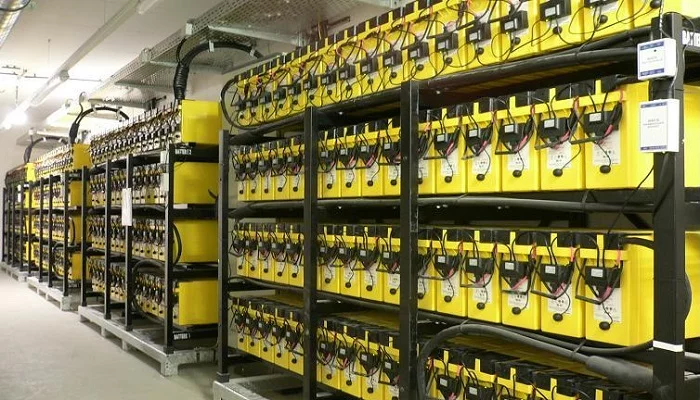
Sizing therefore works like this: voltage comes from the number of units wired in series, ampere-hours come from the number of parallel strings. On a 48 V DC bus, four 6-DMF-52 units in series give 4 × 13.5 V = 54.0 V at float and 4 × 14.1 V = 56.4 V at equalise, and a single string carries 52 Ah. Two strings in parallel give 2 × 52 Ah = 104 Ah, so the bank is a 48 V / 104 Ah assembly built from eight modules. Section §4 spreads that arithmetic out line by line.
Key Takeaways
- 52 Ah is a C3 figure, not a continuous 52 A figure: rated discharge current is 52 Ah ÷ 3 h = 17.3 A per string to a 1.75 V/cell cutoff.
- Series strings set the bus voltage: 6-DMF-52 holds 6 cells, so 6 × 2.25 V = 13.5 V float and 6 × 2.35 V = 14.1 V equalise per unit; four units in series give a 48 V nominal bus.
- Parallel strings set the ampere-hours: 4S × 2P = 48 V / 104 Ah, total mass 8 × 13.7 kg = 109.6 kg.
- Charge current is capped at 10.4 A per unit (52 Ah × 20 %), which sets the minimum charger size for a parallel bank.
- The 6-DMF series is the direct substitute for other 12 V cabinets, and the full 6-DMF range shows where the 52 Ah slot sits against 12, 20, 38 and 45 Ah variants.
- Runtime comes from energy, not from the Ah label: at 42 V end-of-discharge voltage a 104 Ah bank holds 42 V × 104 Ah = 4,368 Wh, and an 80 % planning derate keeps about 3,494 Wh of usable energy.
§1 — 6-DMF-52 Quick Specifications
Every line below is taken from the published model page for the 6-DMF-52. Where a value is derived, the calculation is shown; where the factory has not published a figure, the cell says so rather than estimating.
| Parameter | Published value | Source |
|---|---|---|
| Nominal voltage | 12 V | Model page |
| Nominal capacity | 52 Ah (C3) | Model page |
| Capacity rate | C3 | Model page |
| Rated discharge current | 17.3 A (52 Ah ÷ 3 h) | Arithmetic |
| Dimensions (L × W × H) | 224 × 135 × 175 mm | Model page |
| Weight | 13.7 ± 0.2 kg | Model page |
| Terminal | φ11.8-M6 | Model page |
| Terminal torque | not published | To be requested from the factory |
| Float voltage | 13.5 V (2.25 V/cell) | Model page |
| Equalise voltage | 14.1 V (2.35 V/cell) | Model page |
| Maximum charge current | 10.4 A (52 Ah × 20 %) | Model page |
| Discharge cutoff | 1.75 V/cell | Model page |
| Cycle life | 350–600 cycles (DoD 50–80 %) | Model page |
| Self-discharge | ≤3 %/month at 25 °C | Model page |
| Working temperature | −15…50 °C | Model page |
| Design life | not published | To be requested from the factory |
| Cell configuration | 6 × 2 V cells per 12 V unit | Arithmetic |
| Specific energy | 45.5 Wh/kg for a 4S × 2P bank | Arithmetic |
§2 — The Pain: Why 52 Ah Strings Get Oversized, Undersized, or Mis-Sized
Most 12 V battery buying errors are not made at the model level. They are made between the model and the DC bus, and the 6-DMF-52 exposes three of them.
The Ah label is not the load. A 52 Ah nameplate read as “52 A available” overstates a single 6-DMF-52 string by a factor of three. The published rating is C3, so the string supports 17.3 A for three hours, not 52 A. A 48 V inverter drawing 22.6 A needs two parallel strings even though a single string carries 52 Ah on paper.
Float voltage is the real bus voltage. A 48 V DC bus in a UPS is not held at 48.0 V; it floats at 54.0 V with four 6-DMF-52 units in series, because float is 13.5 V per 12 V unit. Inverters are rated for the floating range, not the nominal label, and a battery bank matched to the nominal number instead of the float number will trip on over-voltage during the equalisation phase, when the same four units sit at 4 × 14.1 V = 56.4 V.
Temperature and age eat capacity in silence. The published 52 Ah holds at 25 °C with self-discharge ≤3 %/month. A bank left on float in a 40 °C room loses capacity faster than the datasheet curve suggests, and the same bank in −15…50 °C ambient will see the usable figure move across the year. Runtime quoted at 25 °C with no temperature note is a number that will disappoint in July.
Runtime is set by the weakest parallel string. One undercharged or high-resistance string in a parallel bank drags the whole bank down, because the strings share the same bus and the same current. That is why string count, string balance and interconnects matter more to runtime than a single extra ampere-hour of nameplate capacity.
§3 — The Choice: Which 12 V Module and Which String Architecture
The 6-DMF-52 is one slot in a documented 12 V range, and the correct choice depends on two decisions: which model fills the cabinet slot, and how many strings the DC bus needs.
On the model side, the 6-DMF series shares one footprint language, and the 6-DMF-38 12V38Ah is the same 224 mm length at 106 mm width and 10.45 kg, so a 38 Ah and a 52 Ah module can sit in adjacent slots of the same cabinet range. The 6-EVF series steps up in capacity but changes the envelope: 6-EVF-50 is 230 × 140 × 180 mm at 15.25 kg, so it is 6 mm longer, 5 mm wider and 5 mm taller than the 6-DMF-52 and will not drop into a 175 mm-high 6-DMF rail. Cabinets designed around the 6-DMF footprint should stay inside that footprint; mixing series only works where the installer has confirmed rail clearance.
On the architecture side, three configurations cover most DC-backup demand:
- Single string (1P). One series string per bus, the low-cost option, but it has no redundancy: any single module failure takes the load down, and the whole bank carries the full load current.
- Two strings in parallel (2P). Doubles ampere-hours to 104 Ah on a 48 V bus and provides the redundancy that single-string designs lack. This is the default recommendation for the 6-DMF-52 in cabinet-scale installations.
- Parallel strings with a DC breaker per string. Adds the ability to isolate one string for maintenance, but the branch protection must be coordinated with the 10.4 A per-unit charge limit so that a charging fault in one string cannot over-charge the other.
A bank that needs more than 104 Ah is normally answered with more parallel strings of the same module rather than with a single much larger unit, because redundancy scales with string count while it does not scale with the size of one module.
§4 — The Framework: DC Bus String Sizing and Runtime Arithmetic
This section works one example end to end: a 48 V nominal DC bus, a 1,000 W inverter with 92 % conversion efficiency, and modules from the 6-DMF range. Every number below is either published or calculated on the spot.
Step 1 — Count the units in series for the bus voltage.
Bus voltage target: 48 V nominal. Units in series: 48 V ÷ 12 V = 4 units. Float voltage of the string: 4 × 13.5 V = 54.0 V. Equalise voltage of the string: 4 × 14.1 V = 56.4 V. Cells in the string: 4 units × 6 cells = 24 cells.
Step 2 — Count the parallel strings for the ampere-hours.
Required DC power at the bus: 1,000 W ÷ 0.92 efficiency = 1,087 W. Current drawn from the 48 V bus: 1,087 W ÷ 48 V = 22.6 A. One 6-DMF-52 string supplies 52 Ah, so one string cannot carry 22.6 A at the C3 rate of 17.3 A. Parallel strings required: 22.6 A ÷ 17.3 A = 1.31 → 2 strings. Bank ampere-hours: 2 × 52 Ah = 104 Ah. Total units: 4 units × 2 strings = 8 modules.
Step 3 — Compute the bank energy and the mass.
Nominal energy: 48 V × 104 Ah = 4,992 Wh. End-of-discharge energy at the 1.75 V/cell cutoff: 24 cells × 1.75 V = 42 V, so 42 V × 104 Ah = 4,368 Wh. Planning energy at 80 % usable: 4,368 Wh × 0.8 = 3,494 Wh. Bank mass: 8 modules × 13.7 kg = 109.6 kg. Specific energy of the bank: 4,992 Wh ÷ 109.6 kg = 45.5 Wh/kg.
Step 4 — Convert energy into runtime.
Runtime on full energy: 4,368 Wh ÷ 1,087 W = 4.0 hours. Runtime on planning energy: 3,494 Wh ÷ 1,087 W = 3.2 hours.
Step 5 — Size the charger.
Per-unit charge limit: 10.4 A (published). Charger requirement for two parallel strings: the total should not exceed 10.4 A × 8 modules = 83.2 A, and a charger set below that figure keeps every module inside its published limit. A 60 A charger is a typical starting point for this bank and stays comfortably inside the 83.2 A ceiling.
Step 6 — Fix the temperature and aging margin.
The 52 Ah rating and the 3.2-hour runtime both hold at 25 °C. For an ambient range of −15…50 °C, the planning figure has to be set from the worst month rather than from the datasheet headline. If the installation runs at 35 °C or above, the 80 % planning factor should be treated as the optimistic case, not the conservative one.
The same framework scales. Changing only the parallel string count from 2 to 3 gives 3 × 52 Ah = 156 Ah, an end-of-discharge energy of 42 V × 156 Ah = 6,552 Wh, a planning energy of 6,552 × 0.8 = 5,242 Wh, a runtime of 5,242 Wh ÷ 1,087 W = 4.8 hours, and a mass of 12 × 13.7 kg = 164.4 kg. Nothing else in the calculation moves.
§5 — Sibling Models in the 12 V Range
The table below lists the published values of the neighbouring modules an installer is likely to compare against the 6-DMF-52. All figures are taken from the model pages of the same 12 V VRLA range; design life is shown as “not published” where the factory has not stated it.
| Model | Capacity | Rate | L × W × H (mm) | Weight | Terminal | Float | Equalise | Charge current | Cycle life | Design life |
|---|---|---|---|---|---|---|---|---|---|---|
| 6-DMF-38 | 38 Ah | C3 | 224 × 106 × 175 | 10.45 ± 0.2 kg | φ9.8-M5 | 13.5 V | 14.1 V | 7.6 A | 350–600 | not published |
| 6-DMF-45 | 45 Ah | C3 | 224 × 121 × 175 | 12.3 ± 0.2 kg | φ11.8-M5 | 13.5 V | 14.1 V | 9.0 A | 350–600 | 2–5 years |
| 6-DMF-52 | 52 Ah | C3 | 224 × 135 × 175 | 13.7 ± 0.2 kg | φ11.8-M6 | 13.5 V | 14.1 V | 10.4 A | 350–600 | not published |
| 6-EVF-50 | 50 Ah | C3 | 230 × 140 × 180 | 15.25 ± 0.2 kg | φ11.8-M6 | 13.5 V | 14.1 V | 10.0 A | 350–600 | 2–5 years |
Three readings of this table decide the choice. First, capacity alone does not decide it: the 6-EVF-50 offers 50 Ah at a 10.0 A charge limit and 15.25 kg, while the 6-DMF-52 offers 52 Ah at 10.4 A and 13.7 kg in a narrower 175 mm height. Second, the charge current scales with capacity — 7.6 A for 38 Ah, 10.4 A for 52 Ah, 10.0 A for 50 Ah — so a charger specification always follows the model. Third, the footprint changes with the series, and the 224 × 135 × 175 mm envelope of the 6-DMF-52 is the one to design the cabinet around.
§6 — The Trust: Factory Basis for Every Number Above
Every specification used in this article comes from the CHISEN product documentation for the 12 V VRLA range, not from a distributor listing or a catalogue round-up. The 6-DMF-52 is produced by CHISEN Battery, Hangzhou, China, which operates 8 production bases with an annual capacity of 70 million kVAh and holds CE, ISO 9001, ISO 14001, UL and IEC certifications. The same line produces flooded tubular OPzS2, gel tubular OPzV2 and the 12 V VRLA 6-DZF, 6-DMF and 6-EVF series.
CHISEN’s export desk ships 12 V VRLA modules to distributors and OEM panel builders in India, Nigeria, Kenya, Vietnam, the Philippines, Brazil, Egypt, Mexico, Indonesia, Pakistan, the UAE, South Africa, Poland, Germany, Spain, Australia, Thailand, Malaysia, Singapore and Hong Kong. Containers normally leave through Ningbo, Shanghai and Shenzhen, with project shipments also loaded at Guangzhou; delivery is worked out as FOB or CIF against port references such as Mumbai, Chennai, Karachi, Lagos, Mombasa, Durban, Cairo, Hamburg, Rotterdam, Antwerp, Valencia, Santos, Callao, Dubai and Colombo.
The factory facts matter for one specific reason: runtime commitments and audit trails need documentation that survives a shipment. A published model page with a stated charge limit, cutoff voltage, self-discharge rate and temperature range can be checked on arrival against the delivered unit. Figures that no factory publishes — terminal torque and design life for the 6-DMF-52 — are marked as not published here and can be requested in writing for a specific project.
§7 — FAQ
Q1: What are the published nominal voltage and capacity of the 6-DMF-52? 12 V and 52 Ah, rated at the C3 rate, which means 52 Ah delivered over three hours down to a 1.75 V/cell cutoff. The rated discharge current is therefore 17.3 A per string (Source: Model page).
Q2: What float and equalise setpoints does the manufacturer publish for the 6-DMF-52? Float 13.5 V and equalise 14.1 V per 12 V unit, which is 2.25 V/cell and 2.35 V/cell across the six cells of each unit (Source: Model page).
Q3: What is the maximum charging current for the 6-DMF-52? 10.4 A, equal to 20 % of the 52 Ah rating (Source: Model page). In the 4S × 2P example of §4 this caps the charger at 83.2 A across eight modules.
Q4: What are the case dimensions and weight of the 6-DMF-52? 224 × 135 × 175 mm and 13.7 ± 0.2 kg (Source: Model page). The same 224 mm length and 175 mm height as the 6-DMF-45, with 14 mm more width.
Q5: What terminal type and torque does the 6-DMF-52 use? φ11.8-M6 terminals (Source: Model page). Terminal torque is not published and should be requested from the factory in writing before installation.
Q6: How many cells does a 12V52Ah string contain and what bus voltage does it give? Six 2 V cells per unit, so a 48 V bus needs four units in series: 24 cells, 4 × 13.5 V = 54.0 V at float and 4 × 14.1 V = 56.4 V at equalise (Source: Model page, Arithmetic).
Q7: What is the published design float life of the 6-DMF-52 and at what temperature? Design life is not published. The published figures are a cycle life of 350–600 cycles at 50–80 % depth of discharge, self-discharge ≤3 %/month at 25 °C and a working range of −15…50 °C (Source: Model page).
Q8: How should an importer verify the 6-DMF-52 on delivery? Check the label against the model page for capacity, terminal type and dimensions, measure open-circuit voltage per cell and confirm the setpoints at 13.5 V float and 14.1 V equalise, then log the weight of each unit against 13.7 ± 0.2 kg before the consignment leaves the port.
Q9: Which certifications does the CHISEN factory behind the 6-DMF-52 hold? CE, ISO 9001, ISO 14001, UL and IEC, produced across 8 bases with an annual capacity of 70 million kVAh in Hangzhou, China (Source: company profile).
Q10: How do I request a quotation or samples for the 6-DMF-52? Send the target string configuration, bus voltage, load and required runtime to the export desk; samples and a project quotation are prepared against the published specification.
Expert Summary
The 6-DMF-52 is a 12 V 52 Ah C3 VRLA module, 224 × 135 × 175 mm at 13.7 ± 0.2 kg, float 13.5 V, equalise 14.1 V, 10.4 A charge limit, 1.75 V/cell cutoff, ≤3 %/month self-discharge at 25 °C, −15…50 °C working range, 350–600 cycles at 50–80 % DoD, design life not published. Sizing separates cleanly into two decisions: series strings set the bus voltage (4 units give a 48 V bus at 54.0 V float), parallel strings set the ampere-hours (2 strings give 104 Ah, 4,992 Wh nominal, 109.6 kg, 45.5 Wh/kg). Against a 1,000 W load at 92 % efficiency, the bank draws 22.6 A, needs 2 strings because one 17.3 A C3 string cannot carry it, and delivers 4.0 hours on full energy or 3.2 hours after the 80 % planning derate. Charge current, cutoff voltage and temperature set the real limits, and every unpublished figure should be requested from the factory rather than estimated.
Contact CHISEN — 24-Hour Response
Sales: sales@chisen.cn | Export desk: jack@chisen.cn | WhatsApp: +86 131 6622 6999 | www.chisen.cn
Technical sizing questions are answered within 24 hours. Send the bus voltage, the load in watts or amps, the required runtime and the cabinet dimensions, and the string configuration will be returned with the supporting arithmetic.
Related CHISEN Buyer Guides
- 12V 50Ah Motorcycle Battery: Choosing Between the 6-EVF-50, 6-DMF-45 and 6-DMF-52 (2026)
- 12V 100Ah LiFePO4 vs Lead Acid Battery: Cycle Life, Published 6-EVF-100 Specs and Where Ea
- 2V 1000Ah Battery Buyer Guide 2026: Telecom, UPS, and Solar Storage Sourcing
- 6-EVF-120 12V120Ah AGM VRLA Battery for UPS: Specs, Float Charging
- 6-EVF-150 12V150Ah AGM Battery: Published Specs, Parallel String Sizing and EVF Range Comp
